
Ferrite Magnetic Separators: Deep-Field Circuit Design, Tramp Iron Force Gradients, and Industrial Bulk Sourcing
Specify ferrite magnetic separators for bulk handling: compare circuit layouts, working-gap tests, housing materials, and RFQ controls. Plan your OEM review.
Ferrite magnetic separators are the workhorse separation systems of bulk solids handling, protecting downstream crushers, pulverizers, shredders, and granulators from damaging tramp metal. In mining, aggregate quarrying, mineral beneficiation, grain milling, biomass processing, and high-throughput municipal recycling, permanent magnetic separators built with sintered ceramic strontium ferrite (SrFe12O19) handle continuous extraction of rogue iron bolts, broken excavator teeth, wire fragments, and processing scrap.
Procurement and mechanical engineering teams should compare magnetic field and capture performance at the working gap, rather than surface Gauss alone. A wide-pole ferrite circuit can be suitable for large tramp iron in deep burdens; a compact rare-earth grate serves a different duty close to the product. Field reach depends on pole pitch, magnet volume, yoke design, and installation geometry. Neither magnet chemistry nor a catalog surface reading establishes capture efficiency.
This engineering guide helps mechanical design engineers, plant operators, and OEM purchasing managers compare cross-belt, pulley, drum, and tube layouts; define working distances; select housing materials; and prepare comparable RFQ packages for custom ferrite magnets and complete assemblies. Compare the total installed cost, including support steelwork, cleaning drives, wear parts, freight, and testing. There is no universal ferrite-to-neodymium purchase-price ratio.
Reviewed: 8 November 2026. Scope: Global OEM sourcing of industrial permanent ferrite magnetic separators, including suspended overband/cross-belt magnets, magnetic head pulleys, rotating drums with stationary internal arcs, and grate/tube assemblies. This is a procurement screening guide, not a certified separator design or a report of plant testing. The public source summaries below establish material-measurement and certification context; they do not certify the example equipment. Final sizing requires project-specific burden, belt velocity, contaminant response, temperature, and trajectory trials. Food and pharmaceutical installations also require the purchaser's applicable hygiene and regulatory assessment.
Sourcing custom ferrite magnetic separators or bulk assemblies?
Specify your burden depth, conveyor belt width, material bulk density, and target tramp metal profile for a dedicated engineering review.
Explore Ferrite Magnetic Separators
1. The Physics of Magnetic Tractive Force: Why Surface Gauss Is Not Enough
In industrial separation specifications, surface magnetic flux density (B, measured in Gauss or Tesla) is useful for repeatable inspections, but it is insufficient for predicting capture through a moving burden. Ask where a reading was taken, which probe was used, and whether the housing and cleaning belt were installed. One tesla equals 10,000 Gauss; comparisons need the same units and measurement position.
For a small, linearly magnetizable particle in a slowly varying field, a simplified one-dimensional screening relationship is:
Fz ≈ (χeff × V / μ0) × Bz × (dBz/dz)
μ0 ≈ 4π × 10^-7 H/m
Here V is particle volume in cubic metres, χeff is an effective susceptibility for the stated shape and field, and dBz/dz is the vertical field gradient in tesla per metre. The sign follows the selected coordinate direction. The scalar expression assumes the vertical field component dominates; other geometries require the full vector field. A field gradient produces translational force, whereas an ideal uniform field can orient an object without lifting it.
Model limitation: Steel bolts are nonlinear ferromagnetic objects. Their magnetization depends on field strength, saturation, shape, orientation, and magnetic history. A constant susceptibility taken from a material table cannot reliably predict their extraction force. The expression explains why working-gap gradients matter; it does not replace finite-element analysis with a suitable material model or physical capture trials.
CONVEYOR CROSS-SECTION: DEFINE THE WORKING DISTANCE
[ Suspended magnet face ]
             |<-- clearance above maximum burden
~~~~~~~~~~~~~|~~~~~~~~~~~~~ top of burden
             |    bulk material flow
             |    [buried tramp iron]
========================== conveyor belt

Working distance: magnet face to the target, including intervening layers.
Capture must overcome gravity, burden resistance, and limited exposure time.
Pole Pitch and Deep-Field Reach
A close-pitched magnetic tube concentrates flux and gradients near its surface, making it useful when product flows close to the tube. A larger pole pitch can project a field farther into a burden, at the expense of assembly volume, mass, and potentially local gradients. A large ferrite overband and a compact neodymium tube are therefore different circuit architectures, not a controlled comparison of magnet materials.
Ferrite's lower magnetic energy density usually requires more magnet volume for a given duty than a rare-earth design. The yoke must carry the return flux without excessive saturation, and surrounding steel can redirect the field. Obtain a map across the whole active width, including the weakest lateral positions, with the final wear plate and cleaning belt fitted. Either magnet family can be engineered for different reaches; do not use a universal exponential decay curve or a single distance threshold for all assemblies.
Illustrative Force-Gradient Comparison
The following inputs are hypothetical, not supplier measurements. At the same target location, assume Circuit A has Bz = 0.008 T and gradient magnitude 0.05 T/m; Circuit B has Bz = 0.045 T and 0.40 T/m. Their field-gradient products are:
- Circuit A:
0.008 × 0.05 = 0.0004 T²/m. - Circuit B:
0.045 × 0.40 = 0.018 T²/m. - Ratio:
0.018 / 0.0004 = 45under the same linear-particle assumptions.
A hypothetical 0.12 kg steel bolt weighs 0.12 × 9.81 ≈ 1.18 N. Neither field-gradient product establishes that either circuit can lift that bolt: the model lacks a validated magnetization response and measured burden resistance. Even an adequate static pull may fail dynamically if exposure time is short. Approximate exposure time as active capture length divided by material velocity, then verify recovery at the maximum specified speed and burden. Record target shape, starting depth, orientation, repetitions, and misses so the comparison is reproducible.
2. Core Magnetic Circuit Architectures for Industrial Separation
Industrial magnetic separators are configured into four primary mechanical and magnetic topologies, each addressing distinct burden depths, particle sizes, and process flows.
Topology 1: Suspended Overband and Cross-Belt Separators
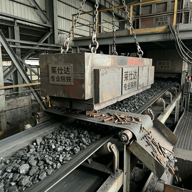
Suspended magnetic separators are installed above belt conveyors carrying run-of-mine ore, crushed stone, coal, shredded municipal solid waste (MSW), or wood chips. They are deployed in two standard orientations:
- Cross-Belt Orientation: The separator is mounted perpendicular to the main conveyor belt, typically across a horizontal trough section. An auxiliary vulcanized rubber cleated belt continuously revolves around the stationary magnetic core. When tramp iron is drawn upward against the cleaning belt, the cleats carry the metal crosswise out of the magnetic field, dropping it into a side collection chute.
- In-Line Orientation: The separator is suspended directly over the conveyor head pulley along the parabolic discharge trajectory. At the discharge point, the bulk material expands and transitions into free-fall, reducing confinement and potentially lowering the force needed to extract buried ferrous contaminants. Compare mounting options using the actual trajectory and surge flow; no universal conveyor-speed cutoff selects the arrangement.
A magnetic core can use ferrite blocks and pole pieces coupled to a low-carbon steel return yoke; the pole layout is design-specific. The backplate functions as a magnetic flux collector, minimizing rear leakage and focusing maximum magnetic energy downward into the process stream.
Topology 2: Magnetic Head Pulleys
A magnetic head pulley replaces the discharge pulley of a belt conveyor. Ferrite assemblies create a field through the shell and conveyor belt:
MAGNETIC HEAD PULLEY SEPARATION DYNAMICS
=========================================
Incoming Burden on Belt  -->  [=== Conveyor Belt ===]
                                    |
                           ( Magnetic Pulley )
                               /          \
      Non-Magnetic Trajectory /            \ Magnetic Tramp Metal
                             /              \ Adheres around underside
                            v                v
                  [ Clean Material Chute ]  [ Tramp Metal Chute ]
(Dropped when belt leaves pulley)- Non-magnetic bulk materials follow a natural parabolic discharge trajectory into a clean product chute.
- Ferrous contaminants are attracted through the conveyor belt and pinned against the outer pulley face.
- As the belt wraps around the pulley and leaves the magnetic zone on the return flight, the magnetic field drops off, allowing the trapped ferrous metals to discharge into a separate reject bin behind an adjustable splitter plate.
Magnetic pulleys operate continuously without separate drive motors for the magnet, making them highly economical. Because the magnet acts through the conveyor belt, belt thickness and construction are part of the working-gap budget. Confirm pulley diameter, drive duty, belt compatibility, and splitter adjustment rather than selecting a magnet grade alone.
Topology 3: Rotating Drum Separators (Stationary Internal Arc)
Unlike a magnetic head pulley, an industrial drum separator features a stationary internal magnetic arc with a supplier-defined capture and release angle housed inside a continuously rotating non-magnetic stainless steel shell. Material is fed either onto the top of the drum (overfeed) or guided along the underside (underfeed).
- Internal Magnetic Arc: Constructed from sized, typically ground sintered ferrite blocks fastened to a rigid central shaft. The arc remains fixed in space while the outer shell rotates on external pillow block bearings.
- Process Dynamics: Non-magnetic particles cascade off the shell face immediately under gravity. Ferrous particles are pinned to the rotating shell by the stationary field, carried past the vertical centerline, and automatically released once the shell carries them outside the influence of the internal magnetic arc.
- Operational Boundary: Drum separators benefit from controlled feed layers, often delivered by a vibratory pan feeder. Feed depth, drum diameter, shell speed, and splitter location must be established together. RPM alone does not establish throughput or recovery.
Topology 4: Magnetic Grates and Tube Separators
For gravity-fed chutes, hoppers, and pneumatic conveying lines handling fine powders, grain, sugar, flour, and plastic pellets, magnetic grates bring ferrous contaminants close to capture surfaces. Very fine or weakly magnetic contamination can require rare-earth circuits or complementary detection; suitability must be demonstrated with representative product.
- Internal Architecture: Sintered ferrite disc or ring magnets are stacked axially inside seamless stainless steel tubes, separated by soft iron pole concentrators. The pole concentrators force magnetic flux to emerge radially, creating intense localized field gradients (
dB/dr) at the tube surface. - Tube Spacing: Staggered tube rows can improve product exposure, but spacing must balance capture distance, flow area, cleaning access, and bridging risk. Specify product particle size, cohesiveness, throughput, and pressure duty where applicable; a nominal spacing cannot guarantee capture or unobstructed flow.
3. Metallurgy, Housing Design, and Austenitic Stainless Steel Controls
The structural casing of a magnetic separator is as critical to separation efficiency as the permanent magnets inside. Incorrect metallurgical specification can result in severe magnetic flux leakage, casing distortion, premature abrasive wear, or bacterial harborage in sanitary food applications.
Control the Finished Shell, Not Just the Alloy Name
Product-contact drum shells, tube envelopes, and wear plates should be selected for low magnetic interference, corrosion resistance, mechanical duty, and cleanability. Austenitic stainless grades such as 304 and 316L are common candidates. A steel return yoke serves a different purpose: its high magnetic permeability is intentional.
Cold work and welding can alter the local magnetic response of an austenitic shell, particularly in 304. Specify a finished-part permeability inspection method, locations, and acceptance limit agreed with the separator designer. The name 316L alone does not guarantee a particular permeability after fabrication. Do not impose a universal μr ≤ 1.02 limit without defining the measurement field and instrument.
If forming has produced an unacceptable response, review alloy selection, fabrication sequence, and any heat treatment before installing magnets, seals, or adhesives. Solution annealing is a specialist fabrication decision, not a routine treatment for a completed separator. Ferritic or martensitic stainless grades can redirect flux; substituting them into a working shell requires circuit analysis and testing. They do not form a universally impenetrable magnetic shield.
Abrasive Wear Liners and Sanitary Surface Finishing
For aggregate, slag, and mineral handling, specify replaceable wear components and include their full thickness in the magnetic gap. Ceramic liners or suitable wear alloys can reduce maintenance, but the designer must confirm retention, impact resistance, magnetic response, and replacement access. An alloy description alone cannot establish wear life.
For hygienic duty, agree product-contact alloy, surface finish, drainability, weld quality, and cleaning access with the purchaser. A finish such as Ra ≤ 0.8 μm may be a contractual target, but it does not by itself prove hygienic compliance or eliminate microbial risk. Require surface measurement locations, weld inspection records, and a cleaning procedure that prevents captured metal from re-entering product during servicing.
HACCP International describes equipment certification and provides access to product registers. Verify the exact model, certificate conditions, intended use, and applicable food zone if certification is claimed. Product certification is distinct from a food business's HACCP program. This guide has not reviewed the full text of 0909MAGSEP and does not attribute a universal roughness or pull-test threshold to that standard.
4. Temperature Boundaries and Environmental Demagnetization Resistance
Specify minimum ambient temperature, continuous product temperature, short-duration peaks, washdown exposure, and the expected temperature at the magnet core. A hot bulk stream does not necessarily bring the whole assembly to the same temperature; insulation and duty cycle matter.
The High-Temperature Ceramic Advantage
Many sintered ferrite grades have a positive temperature coefficient of intrinsic coercivity, while remanence decreases with increasing temperature. This can make ferrite attractive for hot processing duties, but it does not make the material or finished separator immune to demagnetization. Grade, circuit load line, opposing fields, thermal cycling, and mechanical assembly limits still matter.
Do not use Curie temperature as an allowable operating rating. Adhesives, encapsulation, bearings, belts, and seals may impose lower limits than the magnet. NdFeB also includes grades for elevated temperatures; reject or approve a proposed circuit against its actual hot operating point and assembly rating, rather than excluding the entire material family above 120°C.
Ask the supplier for magnetic-property curves over the specified range, a statement of allowable irreversible loss, and an agreed hot-condition capture test. Define whether measurements are taken while hot or after cooling: recovery of room-temperature flux is not evidence of adequate capture during hot operation. IEC 60404-8-1:2023 provides the material specification context; its public scope does not rate a finished separator.
The Low-Temperature Design Guardrail
Ferrite can become more vulnerable to irreversible loss at low temperature because intrinsic coercivity decreases. For outdoor service, require the supplier to check the selected grade's demagnetization curves at the minimum temperature against the actual circuit operating point and opposing fields. There is no universal permeance-coefficient threshold that approves all ferrite separators.
Agree cold-soak conditions, handling and assembly restrictions, and before/after measurements. Test representative captured objects at the required operating gap where cold service is critical. Keep the resulting records tied to the delivered grade and circuit revision so later cost substitutions cannot silently remove the winter-duty margin.
5. Engineering Sizing Matrix: Industrial Ferrite Separators
Use this seven-configuration matrix to decide what evidence to request. It is an RFQ comparison aid, not a table of standardized maximum burden depths or guaranteed capture distances. Grade names such as Y30 and Y35 require the supplier's property limits and test conditions; they are not interchangeable equipment ratings.
| Separator Configuration | Suitable Duty to Investigate | Main Geometry Input | Capture Boundary to Test | Cleaning / Wear Control | Evidence Before Release |
|---|---|---|---|---|---|
| Suspended magnet, manual clean | Intermittent larger tramp iron in bulk solids | Face-to-belt distance and peak burden | Buried target at weakest width position | Safe isolation and cleaning frequency | Working-gap map and loaded capture trial |
| Suspended cross-belt, self-cleaning | Continuous removal above a conveyor | Suspension, pole pitch, cleaning belt thickness | Full-speed extraction and transport to reject chute | Cleat clearance, belt wear, metal discharge | Trial with final cleaning belt installed |
| In-line discharge overband | Extraction in an opening discharge stream | Head-pulley trajectory and magnet angle | Surge trajectory and target escape path | Reject chute clearance and guarding | Approved trajectory drawing and capture trial |
| Magnetic head pulley | Ferrous recovery at conveyor discharge | Belt construction, pulley diameter, splitter | Target retention through the discharge arc | Shell wear, belt tracking, bearing duty | Belt compatibility and reject separation trial |
| Rotary drum, overfeed | Controlled feed of ferrous-contaminated solids | Feed depth, shell speed, internal arc | Carry-over and clean-product losses | Replaceable shell or liner access | Recovery and product-loss records |
| Rotary drum, underfeed | Mineral or process-specific separation duty | Feed path, residence time, fluid duty if wet | Recovery at actual feed composition | Abrasion, seals, liner thickness | Representative material trial and mass balance |
| Grate / tube array | Gravity flow with close product-to-tube exposure | Tube pitch, rows, flow area, product size | Smallest specified contaminant and bridging | Accessible cleaning and retained-metal control | Product trial, finish records, certification scope if claimed |
For quote comparison, send the same target and feed envelope to every supplier. Separate required recovery from acceptable product loss; a separator that captures tramp iron while rejecting excessive saleable material may be commercially unsuitable. Request proposed layout drawings before comparing equipment prices.
6. OEM Procurement and Engineering Verification Checklist
Before releasing a formal Request for Quotation (RFQ) for custom ferrite magnetic separators, project engineering and sourcing teams should agree these eight parameters:
- 1. Bulk material properties: Record bulk density, lump-size distribution, moisture, cohesiveness, and normal/peak throughput. Include a representative sample or a documented trial-material specification.
- 2. Conveyor geometry and trajectory: Supply belt width, speed, trough angle, belt thickness, reinforcement, nearby steelwork, and discharge drawings. Steel-cord belts require a compatibility assessment with both belt and separator suppliers; an in-line position alone does not establish compatibility.
- 3. Burden depth at surge: For an approximate rectangular bed,
Davg = Q / (ρ × v × Weff), with mass flowQin kg/s, densityρin kg/m³, speedvin m/s, and effective widthWeffin metres. Convert tonnes/hour by dividing by 3.6. This estimates average depth, not the peak of a troughed or uneven bed; measure the maximum profile separately. - 4. Target contaminant response: Define material, shape, dimensions, mass, and starting depth. Some manganese-rich wear fragments and nonferrous metals respond poorly or not at all; do not assume every metal object can be captured magnetically. Agree the actual test pieces and repetitions.
- 5. Working-gap budget: Dimension magnet face, bottom plate, cleaning belt, cleats, liners, and target position from a common datum. Avoid double-counting layers. Require clearance over the maximum lump size and a documented gap in the capture test.
- 6. Housing and fabrication controls: Require traceable material certificates, agreed finished-shell magnetic inspection, weld records, and sanitary finish measurements where relevant. Define wear allowance and field access for replacement parts.
- 7. Temperature envelope: State minimum, continuous, peak, and cleaning temperatures. Require grade-specific curves and component ratings, plus cold/hot validation when needed. Agree acceptable irreversible flux loss rather than assuming complete recovery.
- 8. Factory acceptance testing (FAT): Agree the field-map grid, reference plane, instrument calibration, target pull-test geometry, and loaded dynamic capture procedure. Record every trial and miss, cleaning/reject behavior, and product loss. A static pull test is a repeatability check, not a process-recovery certificate.
For example, a hypothetical Q = 100 kg/s, ρ = 1,600 kg/m³, v = 1 m/s, and Weff = 0.8 m gives Davg = 0.0781 m, or about 78 mm. A surge ridge may be substantially deeper; the 78 mm result must not be copied into the contract as maximum burden without measuring the actual profile.
Bulk Sourcing and Purchase Release
Separate prototype engineering, first-article testing, and repeat production prices. Ask whether the quotation covers magnet blocks, a magnetic core, or a complete guarded separator with drives and controls. List tooling, FAT attendance, spare belts or shells, packing, freight, installation, and commissioning separately. State currency, quotation validity, delivery terms, and the named delivery location so landed-cost comparisons use the same assumptions.
For repeat orders, require traceability for magnet grade, magnetization direction, yoke material, shell thickness, and circuit revision. Specify a signed sample or approved drawing and a change-notification rule: a stronger catalog grade does not automatically approve a smaller block, different pole pitch, or thicker liner. Agree warranty scope, wear exclusions, spare-part availability, and how a failed acceptance test will be resolved before payment milestones are released.
Send your conveyor drawing and test-piece list for an RFQ review, or use the OEM ferrite RFQ checklist to prepare a comparable supplier brief.
Visual Decision Aids
The diagram shows the sourcing sequence. In the envelope review, resolve burden depth, trajectory, working gaps, shell material, and temperature. The pilot gate requires the agreed material and contaminant trial; the final supplier plan must preserve the tested circuit revision. The product images illustrate equipment layouts and do not document a FerriteCustom installation or measured capture performance.
Decision Snapshot
| Operating Constraint | Engineering / Circuit Action | Sourcing Release Boundary |
|---|---|---|
| Deep or uneven burden | Compare pole layouts and target distance at surge | Require capture trials at the weakest specified location |
| High material velocity | Compare cross-belt and discharge-trajectory options | Validate exposure time and the full reject path |
| Hot bulk solids | Review grade curves and all assembly component ratings | Require agreed hot-condition evidence, not a Curie-temperature claim |
| Abrasive mineral flow | Include replaceable liner thickness in the gap budget | Fix wear allowance and replacement inspection intervals |
| Sanitary food / pharma duty | Agree alloy, finish, cleaning access, and applicable requirements | Verify claimed certification scope and purchaser hygiene approval |
| Cold outdoor service | Check the grade and operating point at minimum temperature | Require documented cold-duty verification without a universal Pc cutoff |
Engineering and Sourcing Recommendation
Select magnetic separator technology based on effective field reach at peak burden depth rather than catalog surface Gauss ratings.
Recommended Action
Provide conveyor belt width, speed, material burden depth, bulk density, peak lump size, and process temperature in your RFQ. Mandate factory Gauss mapping at actual working suspension heights and verify non-magnetic shell metallurgy prior to shipment.
Caution
Surface Gauss and magnet chemistry alone cannot guarantee extraction. Require representative dynamic capture testing at the agreed burden, speed, working gap, and temperature.
For custom bulk material handling and magnetic separation equipment, review our specialized manufacturing programs across Ferrite Magnetic Separators, Ferrite Block Magnets, Ferrite Bar Magnets, and Ferrite Magnetic Assemblies. Contact our engineering team with your conveyor drawings and process parameters to discuss circuit options, test requirements, and quotation scope.
Frequently Asked Questions
Can a lower surface-Gauss ferrite separator outperform a compact neodymium unit?
It can in a particular installation if its pole geometry and volume provide a more suitable field at the target. That does not establish a general material ranking. Compare the field across the working width and gap, then test the actual target objects in the specified product stream. A compact tube and a large suspended overband are not equivalent designs.
When should an engineering team choose in-line rather than cross-belt mounting?
Investigate in-line mounting when extraction at the head-pulley discharge can take advantage of a less confined stream. Check space, trajectory, reject routing, and belt construction. Speed or burden depth alone does not select the arrangement; the chosen layout must pass the agreed surge-condition trial.
Does a 316L stainless steel shell guarantee low magnetic interference?
No. Alloy selection is only one input. Forming, weld condition, thickness, and nearby ferromagnetic components can affect the finished circuit. Agree a finished-part inspection method and limits with the designer, and measure the assembled working field. Do not heat-treat a completed separator without an approved fabrication procedure.
Are ferrite separators immune to high-temperature demagnetization?
No. Ferrite can be a useful hot-duty choice, but its usable temperature depends on grade, magnetic operating point, and assembly components. Require rated hot-condition capture performance and an agreed irreversible-loss limit. A room-temperature check after cooling cannot establish separation efficiency while hot.
What FAT evidence should an OEM buyer request?
Require calibrated field mapping at the stated reference distances, a repeatable pull test with an agreed target and orientation, and a dynamic trial covering feed, burden, velocity, and representative contaminants. Record recovery, misses, product loss, cleaning behavior, temperature, and circuit revision. Material and sanitary records support fabrication acceptance; they do not substitute for capture evidence.
Evidence and Applicability Notes
Evidence and Applicability Notes
Last reviewed: 2026-11-08
Sources Used
- IEC 60404-8-1:2023: public scope for permanent-magnet material properties and dimensional tolerances.
- IEC 60404-5:2015: public scope for measuring permanent-magnet properties, demagnetization curves, and recoil lines.
- HACCP International: public equipment-certification information and distinction from a food business HACCP program.
Method
- Used a simplified linear-particle relationship to explain field-gradient screening; no steel-bolt lifting force is claimed.
- Calculated a hypothetical field-gradient ratio and average-bed-depth example with explicit inputs and units.
- Mapped circuit choices to RFQ inputs and acceptance evidence; no first-party plant test or supplier certification is claimed.
Applicability Boundary
- This guide covers permanent ferrite separator procurement screening, not electromagnetic systems or certified final designs.
- Example arithmetic is hypothetical. Capture depends on target magnetization, orientation, burden resistance, exposure time, and operating conditions.
- Only public source scopes were reviewed, not paid standards clauses. Material standards do not prescribe complete separator FAT or guarantee food safety.
Related Internal Guides
- Ferrite Magnetic Separators Catalog
- Ferrite Block Magnets Engineering Specifications
- Ferrite Bar Magnets for Custom Assemblies
- Ferrite Magnetic Assemblies Manufacturing Overview
- Ferrite Pot Magnets and Channel Assemblies Sizing Guide
- Ferrite Magnet Tolerance Guide for Mass Production
- Visual Acceptance Standards for Ferrite Magnets: Chipping and Cracks
- Low-Temperature Demagnetization in Ferrite Magnets
- Ferrite RFQ Checklist for OEM Buyers
External References
The following public pages were checked on 8 November 2026. The IEC pages verify the scope of material standards; the HACCP International page explains equipment certification. None supplies measured field maps or recovery data for the illustrative circuits in this guide. Obtain the applicable full standard and project-specific evidence before contract approval.
- IEC 60404-8-1:2023 — Permanent Magnet Material Specifications: Material-property and dimensional-tolerance scope; use this context when requesting grade documentation, not as a finished-separator rating.
- IEC 60404-5:2015 — Measurement of Permanent Magnet Properties: Scope includes flux density, polarization, field strength, demagnetization curves, and recoil lines. An assembled field map or dynamic FAT needs a separately agreed procedure.
- HACCP International — Equipment Certification: Public explanation of non-food product certification, intended-use conditions, and the distinction from a food business HACCP program. Verify individual product claims through the linked registers and certificate conditions.
Author

Categories
More Posts

Visual Acceptance Standards for Ferrite Magnets: Managing Edge Chipping and Cracks
Define visual defect limits for custom ferrite magnets: classify edge chips and cracks, set AQLs, and align supplier inspection before RFQ or PO release.


OEM Ferrite Supplier Audit Checklist
A buyer-side audit checklist covering process control, quality systems, and delivery reliability for ferrite magnet suppliers.

Draft Research: Ferrite Packaging Logistics
Draft notes
Inquiry Email
Copy the email, or open your default email app to start an inquiry.