
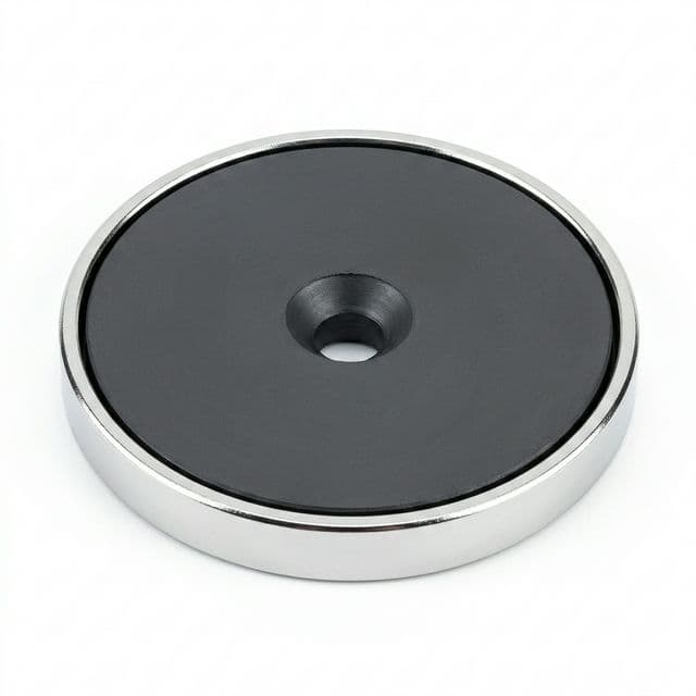
Ferrite Pot Magnets and Channel Assemblies: Magnetic Circuit Sizing, Holding Force Physics, and Sourcing Controls
Specify custom ferrite pot magnets and channel assemblies: optimize steel cup thickness, calculate air-gap decay, prevent shear slip, and secure OEM RFQs.
Ferrite pot magnets (also known as cup magnets) and ferrite channel assemblies use a steel return path to concentrate magnetic attraction at a working face. For custom ferrite magnets, the useful specification is the holding force on the actual workpiece, with its coating, thickness, load direction, and mounting geometry. A catalog pull rating alone does not establish that performance.
A steel cup can improve contact pull compared with an unshielded ceramic core, but there is no universal force multiplier. The benefit depends on pole area, steel saturation, leakage, and the target plate. Pot magnets can also lose substantial force across paint or protective rubber, while a load parallel to the surface depends on friction or a mechanical stop.
This guide gives mechanical engineers, fixture builders, and OEM purchasing teams a way to size the return path, compare pot and channel architectures, define acceptance tests, and send comparable RFQs.
Reviewed: 5 November 2026. Scope: Global OEM sourcing of sintered strontium ferrite pot magnets, rectangular channel assemblies, and sandwich holding assemblies for fixtures, latches, and enclosures. Calculations below are illustrative screening examples, not measured product ratings, lifting approvals, or supplier test records. The cited standards cover material properties and test methods; application holding limits require a separately agreed assembly test.
Sourcing custom ferrite pot magnets or channel assemblies?
Prepare your holding force target, mounting constraints, steel thickness, and annual volume before requesting a quote.
Explore Ferrite Pot Magnets
1. Magnetic Circuit Physics: How the Steel Cup Concentrates Flux
A bare permanent magnet has a field extending from both pole faces. A pot magnet redirects flux from the rear pole through a ferromagnetic steel base and wall to the front rim. The ceramic face and surrounding rim then present opposite poles to the target. When the target bridges them, it completes a short magnetic circuit.
Rear of assembly: steel base connects magnet rear pole to cup wall
                              |
Working face:       [steel rim S] [ferrite face N] [steel rim S]
                              |       |       |
Target workpiece:    ========= ferromagnetic steel =========
Flux loop: ferrite N -> target -> steel rim -> base -> ferrite S
This is a schematic for an axially magnetized core, not a field simulation. The cup can reduce rear and side leakage, but it does not eliminate stray fields. Keep magnetic sensors and sensitive equipment outside a clearance established by measurement.
Maxwell Pressure as a Screening Model
For an approximately uniform, normal gap field, the magnetic pressure estimate is:
F ≈ Bgap² × Aeffective / (2 × μ0)
Here, F is force in newtons, Bgap is the gap flux density in tesla, Aeffective is the effective working pole area in square meters, and μ0 is approximately 4π × 10⁻⁷ H/m. For a nonuniform field, the pressure must be integrated over the working surface; tangential fields and leakage also matter.
Reproducible example: assume Bgap = 0.25 T across an effective area of 500 mm², or 0.0005 m². The equation gives approximately 12.4 N. Neither input is a measured value for a product on this page. Replacing 0.25 T with an assumed 0.35 T nearly doubles the estimate, showing why an unverified field assumption cannot support a guaranteed pull rating.
Do not substitute the ferrite material's remanence, Br, for the interface field. Remanence is a material property; operating flux depends on the demagnetization curve and the entire magnetic circuit. Nor does putting both poles on one working face automatically double the usable area or force.
2. Steel Casing Sizing and Magnetic Saturation
An undersized steel return path can saturate, increasing leakage and limiting useful attraction. The cup base, sidewall, central fastener features, and target plate all belong to the circuit. Checking the outside diameter alone misses narrow sections around mounting holes and formed corners.
Wall Area vs Magnet Pole Area
A first screening balance is:
Φmag ≈ Bd × Amag; Areturn ≥ Φmag / Bdesign
Bd is the assumed operating flux density of the ferrite, Amag is its pole area, and Bdesign is the chosen design flux density for the steel. These are engineering inputs, not universal values prescribed by a material grade. Use the supplier's demagnetization curves and steel B-H data to replace initial assumptions.
For a ring, Amag = π × (Dmag² − dhole²) / 4. For an uninterrupted round cup wall, Awall = π × (Douter × tw − tw²), where tw is wall thickness. These areas must use consistent units. A thin-wall approximation can use the wall's mean circumference times thickness.
Worked sizing example: a hypothetical 32 mm outer diameter, 14 mm inner diameter ferrite ring has a pole area of approximately 650.3 mm². Assuming Bd = 0.35 T and Bdesign = 1.50 T gives a required return area of about 151.7 mm². For a 40 mm outer diameter cup, the annular wall expression gives a screening thickness of approximately 1.25 mm.
That result is a lower-bound area check before leakage, local flux concentration, forming variation, mechanical strength, and manufacturing margin. It is not a released cup dimension. The base carries radial flux through sections whose circumference and enclosed flux vary with radius; it needs its own check. Use magnetic analysis and prototype pull tests before freezing tooling.
Casing Material Selection
- Low-carbon steel: a practical starting point for a magnetic return path. Specify the actual grade, sheet or bar product form, forming condition, and coating. Require magnetic property data where performance is sensitive to material substitution.
- Austenitic stainless steel such as 304 or 316: generally unsuitable as a direct substitute for the ferromagnetic return path. Cold work can change magnetic response, so neither grade name nor a simple attraction test qualifies the circuit. An outer stainless cover around a separate magnetic return path is a different design.
- Ferritic stainless steel such as 430: may provide a magnetic return path, but its magnetic curve, corrosion behavior, processing condition, and required section size need qualification. Do not assume it is interchangeable with low-carbon steel or automatically suitable for marine exposure.
IEC 60404-8-1 addresses permanent magnet material properties and tolerances. It does not approve the completed cup geometry or establish a universal equivalence between commercial Y-grade labels and IEC material designations. Put the agreed magnetic property limits and measurement conditions on the purchase specification.
3. Product Architecture: Pot vs Channel vs Sandwich Assemblies
Choose the pole layout around the workpiece and mounting method. A longer assembly can spread contact along a panel edge, but a warped panel may contact only part of that length. Multiple mounting points improve restraint only when the bracket and fasteners also resist the applied moment.
| Assembly Type | Typical Core | Working Circuit | Main Trade-off | Mounting Approach | Suitable Design Question |
|---|---|---|---|---|---|
| Circular countersunk pot | Ferrite ring | Center face and surrounding steel rim | Compact mounting; ceramic relief is critical | Screw seated on designed steel feature | Can the head clear the ceramic and target? |
| Circular pot with stud | Ferrite disc or ring | Coaxial pole layout | Rear attachment; stud joint needs verification | Welded, formed, or retained stud | What pull and bending loads reach the joint? |
| Circular pot with internal thread | Ferrite core around a steel feature | Geometry depends on boss and core | Thread engagement competes with envelope | Rear threaded boss | Can the fastener bottom out or distort the cup? |
| Rectangular channel | Ferrite block or blocks | Linear center and return poles | Distributed contact; sensitive to flatness | One or more channel mounting holes | Is the full target edge close enough to engage? |
| Sandwich pole assembly | Ferrite block between steel plates | Opposite poles routed to selected edges | Pole orientation sets the useful face | Brackets or retained pole plates | Which edges must bridge the target? |
| Bare ferrite disc or block | Unshielded ceramic | Open field geometry | More exposed field; separate retention needed | Adhesive, clips, or supported pocket | Is stand-off sensing more useful than contact pull? |
These are architecture comparisons, not ranked holding-force efficiencies. Compare samples using the same target, gap, and test method before assigning a winner.
4. Sizing and Mechanical Capability Matrix for an RFQ
There is no reliable diameter-to-holding-force conversion without a specified core, cup, and target. Instead of treating an unsourced size table as a catalog, require the following seven fields from every bidder. This makes quotations comparable and exposes assumptions before tooling is purchased.
| Required Field | Buyer Input | Supplier Evidence | Release Boundary |
|---|---|---|---|
| Assembly envelope | Maximum OD or channel length, width, and height | Dimensioned assembly drawing | Fit all tolerance extremes in the bracket |
| Core and magnetization | Material property limits and pole direction | Grade data and demagnetization curves | Resolve commercial grade equivalents explicitly |
| Steel return path | Stock form, material, wall and base constraints | Steel specification and circuit review | Check local saturation and formed sections |
| Normal pull | Minimum application force in N | Pull results on the specified target | Keep reference-block ratings separate |
| Air gap and target | Coating stack, minimum sheet thickness, flatness | Force-versus-gap and sheet-thickness results | Test the worst allowed combination |
| Shear and moment | Sliding force, offset distance, vibration | Assembly slip, peel, and retention results | Define stops and additional retention as needed |
| Fastener and joint | Head geometry, engagement, installation access | Validated torque window and joint drawing | Check ceramic clearance and cup distortion |
A supplier's reference-block rating can help compare production lots if the fixture is locked. It cannot replace a test on the application panel. Request the fixture drawing with each quotation so a higher reported force is not simply the result of a thicker, cleaner test plate.
For quotation preparation, use the Ferrite RFQ Checklist for OEM Buyers to collect these inputs before contacting suppliers.
5. The Two Critical Physics Traps: Air Gaps and Substrate Thickness
Air Gaps: Request a Curve, Not a Fixed Derating Factor
Paint, adhesive films, rubber covers, roughness, and cup recess all increase the effective separation. Compact adjacent poles can close flux locally rather than through a distant workpiece. The exact force loss depends on the complete geometry; there is no universal percentage remaining at 0.5 mm or 1.5 mm.
An empirical relation such as F(z) = F0 × exp(−kz) can describe a limited measured interval for one assembly. Its fitted constant k has inverse-length units and must come from that assembly's data. Neither that exponential nor a bare-magnet inverse-square rule is a general design law for all gaps.
Ask for measurements at zero gap, nominal gap, and maximum permitted gap. Use nonmagnetic spacers with recorded thickness and account for coating on both mating surfaces. Keep lateral alignment and target material fixed while varying the gap.
Thin Targets: Check the Entire Return Path
A thin target can restrict flux and reduce pull compared with a thick reference plate. The limiting thickness depends on pole spacing, effective return area, target material, and where flux spreads through the workpiece. A rule that target thickness only needs to equal cup wall thickness is insufficient.
For an enclosure using 1.2 mm painted steel, test that production panel at its minimum thickness and maximum coating build. A polished 12 mm reference block may still be used for lot comparison, but it represents a separate test condition. If force is inadequate, compare pole spacing, footprint, target backing, and number of magnets; increasing diameter alone may not solve a saturated or flexible panel.
6. Breakaway Pull vs Shear Force: Preventing Vertical Slippage
Normal pull separates the magnet perpendicular to the target. Shear slides it along the surface. A wall-mounted bracket can also apply an overturning moment because the supported mass sits away from the wall; this can peel one edge before the nominal pull or slip threshold is reached.
For an aligned assembly with no other normal loads, a simple static slip estimate is:
Fs ≈ μ × Fn
Fn must be the normal clamping force at the actual gap, temperature, and target condition. The coefficient μ depends on the two surfaces, contamination, wear, and coating. It is not a fixed fraction attached to the magnet's part number.
Hypothetical example: if an assembly provides 100 N of application clamping force and testing establishes μ = 0.20, the friction estimate is 20 N before applying an application-specific design margin. This is not a safe working load. Dynamic loading, peel, external separation loads, and variation require separate assessment.
Rubber Boots Do Not Automatically Improve Shear
A cover can increase friction while reducing magnetic attraction by adding a gap. Compare the products μcovered × Fn,covered and μbare × Fn,bare. If the bare example gives 0.20 × 100 N = 20 N, but a cover gives an assumed 0.60 × 25 N = 15 N, the covered assembly has less estimated slip resistance despite the higher friction coefficient. Both cases are calculations, not measured outcomes.
A mechanical shoulder, dowel, or supported recess can carry sliding loads while the magnet provides normal clamping. Decide this from the load case and consequence of detachment, rather than an arbitrary force threshold. Do not infer lifting or overhead retention suitability from a breakaway test.
7. Fastening Geometry: Preventing Countersunk Ceramic Fractures
Ferrite is brittle and vulnerable to local tensile stress, bending, and wedging. A countersunk head that bears on an unsupported ceramic bevel can crack the core during tightening. A fastener that stands proud can also hold the entire working face away from the target.
Drawing Requirements for Robust Fastening
- Steel load path: show the intended head seating surface in section. Provide clearance to the ceramic through the full tolerance stack and ensure the cup can carry the clamp load.
- Head geometry: specify the screw standard, angle, head diameter, and height. Do not assume all countersunk screws share the same angle or fit the same ceramic recess.
- Torque window: qualify the minimum torque needed to retain the joint and the maximum that avoids cup distortion, thread damage, or ceramic fracture. Screw size alone does not establish a universal magnet assembly torque.
- Alternatives: a rear stud or threaded boss can avoid routing installation load through the core, but its attachment and bending capacity still need verification. A flange head also needs a steel bearing feature; a broad head does not make direct ceramic loading acceptable.
Use controlled installation tools and inspect samples after tightening and environmental cycling. Record adhesive use, thread engagement, bracket stiffness, and the fastener finish with the validated torque window so production cannot silently change the joint.
8. Potting Resins, Plating, and Corrosion Standards
The ceramic core, steel cup, bond line, coating, and fasteners need to survive the same environment. The assembly temperature limit can be lower than the ferrite material limit because adhesive creep, differential expansion, and coating damage can occur first. A Curie temperature is not an assembly operating rating.
Potting Resin Selection
Epoxy, polyurethane, and silicone formulations offer different stiffness, temperature capability, and chemical resistance. Specify the exact formulation, surface preparation, cure, bond-line geometry, and continuous versus excursion temperatures. Potting can reduce moisture ingress and rattle, but ordinary polymer potting should not be described as hermetic without a qualified sealing test.
Ask for retention results after relevant humidity, thermal cycling, and fluid exposure. A room-temperature adhesive datasheet strength does not establish the strength of a curved cup joint or a long-term hot assembly.
Surface Treatment: Define the Acceptance Endpoint
ISO 9227:2022 describes salt-spray test methods. It does not assign a universal passing duration to a coating or predict outdoor service life. Specify exposure duration, white or red corrosion criteria, inspected areas, edge treatment, and whether samples are tested before or after assembly damage.
| Surface Option | Specification Detail | Magnetic / Mechanical Concern | Evidence to Request |
|---|---|---|---|
| Zinc with conversion coating | Thickness, conversion chemistry, sealer | Build changes working gap and thread fit | Agreed corrosion endpoint on finished parts |
| Electroplated nickel multilayer | Actual layer sequence and thickness | Edges, pores, and adhesion can govern failure | Layer record and application exposure results |
| Electroless nickel | Deposit chemistry and thickness | Distinct process from a Ni-Cu-Ni stack | Adhesion and chemical compatibility results |
| Cathodic e-coat | Pretreatment, film build, cure | Insulating film adds separation at poles | Edge coverage and assembled-part test |
| Qualified ferritic stainless cup | Alloy and processing condition | Different magnetic curve and section needs | Magnetic and corrosion qualification |
| Rubber or polymer cover | Material, hardness, thickness | Friction gain competes with reduced pull | Pull and slip tests after wear and exposure |
A coating name or color is not evidence of regulatory compliance, suitability for food contact, or marine durability. Require applicable declarations and application tests where relevant; compare actual quotations rather than assigning fixed cost multipliers to finishes.
9. OEM Sourcing and Quality Inspection Protocols
Agree tests and decision rules before pilot production. Keep material characterization separate from assembly qualification: IEC 60404-5:2015 covers magnetic material measurements, including demagnetization behavior, rather than prescribing a universal pot-magnet breakaway acceptance plan.
1. Direct Breakaway Pull Test
Use a calibrated force gauge or load cell and an aligned test stand. Record target grade, dimensions, surface roughness, flatness, coating, gap, temperature, dwell, and pull speed. A supplier and buyer might agree a 5 mm/min displacement rate as a starting fixture setting, but that value is not presented here as a standard requirement.
Test normal pull without angular peel, then assess peel and sliding separately if the product experiences those loads. Include both the controlled reference fixture and actual application panels. Define sample count, per-part minimum, permitted variation, retest rules, and calibration traceability in the control plan. A sample mean alone can hide weak individual assemblies.
2. Magnet-to-Cup Retention
Check how the ceramic is retained under service loads and after aging. A push-out test may be useful where the geometry permits it: support the cup, load the core with a suitable punch, and record displacement and failure mode. Establish the acceptance force from the retention requirement and qualified joint; there is no universal 500 N or 1200 N threshold based only on outside diameter.
A cracked core, adhesive failure, and cup deformation indicate different problems. Record them separately. If the cup has no suitable access hole, use a qualified alternative fixture instead of improvising a punch through a blind base.
3. Pole Step and Working-Face Inspection
Specify the ceramic-to-rim step from the magnetic and mechanical design. A small recess can protect the ceramic, while an excessive recess adds a magnetic gap; a protruding core can prevent rim contact and take impact loads. Establish the permitted step from tolerance analysis and application testing, rather than copying one universal coplanarity limit.
For channels, also inspect twist and flatness along the full working length. Correlate dimensional measurements with pull tests to identify whether variation comes from the core, steel forming, coating build, or assembly seating.
10. OEM RFQ Engineering Checklist
Before releasing a purchase order for custom pot or channel tooling, include these eight functional criteria:
- Load case: normal pull, sliding force, offset moment, vibration, and any required additional retention; state loads in newtons and the design margin rationale.
- Target: steel grade, minimum thickness, flatness, surface condition, and coating stack from the production workpiece.
- Gap budget: nominal and maximum separation, including protective covers, paint on both surfaces, dirt allowance, and dimensional variation.
- Steel return path: cup material, stock form, section constraints, and approval process for substitutions.
- Ferrite properties: grade designation, agreed magnetic limits, demagnetization curves over the temperature range, and magnetization direction. Reference IEC 60404-8-1 with the actual agreed material designation.
- Fastening: screw head geometry, steel bearing surface, ceramic clearance, engagement, and validated installation torque window.
- Environment: adhesive formulation and cure, temperature cycle, fluid exposure, coating specification, and agreed ISO 9227 test duration and corrosion endpoint.
- Acceptance and logistics: sample plan, drawing revision, reference and application pull tests, retention checks, lot traceability, and dividers that prevent magnet-to-magnet impacts in transit.
Visual Decision Aids
Apply the diagram's gates to this assembly: validate the envelope and steel return path; test the pilot lot on the production panel at the allowed gap; then lock the supplier drawing, joint specification, fixture, and acceptance plan. The flow is a process illustration, not evidence of a completed customer qualification.
Decision Snapshot
| Program Constraint | Engineering / Drawing Action | Sourcing Release Boundary |
|---|---|---|
| Thin target sheet | Compare pole spacing, footprint, and backing | Accept only application-panel results |
| Vertical wall load | Evaluate friction, moment, and mechanical stops | Confirm slip and peel as separate load cases |
| Countersunk mounting | Keep head seating load on qualified steel features | Approve a torque window on assembled samples |
| Outdoor or washdown exposure | Define coating, adhesive, and fluid conditions | Agree corrosion and aged-retention endpoints |
| Protective cover required | Include cover thickness in the gap budget | Compare covered and bare slip performance |
| Long channel assembly | Control twist, straightness, and bracket stiffness | Test minimum engaged contact and panel variation |
Engineering and Sourcing Recommendation
Design ferrite pot magnets from the target substrate and load vector backward to the steel cup geometry.
Recommended Action
Provide envelope limits, fastener geometry, target sheet thickness, working gap, environment, and load profile in the RFQ. Approve the drawing and pilot-lot results on your actual workpiece before mass production.
Caution
A reference-block pull rating does not qualify a painted sheet-metal installation. Installation torque, sliding, peel, and magnet retention need their own acceptance criteria.
For custom tooling and magnetic holding assemblies, compare our Ferrite Pot Magnets, Ferrite Channel Magnets, and Ferrite Magnetic Assemblies. Send your drawing and application requirements for review, including the target panel and gap, so the quotation can identify what still needs testing.
Frequently Asked Questions
Evidence and Applicability Notes
Evidence and Applicability Notes
Last reviewed: 2026-11-05
Sources Used
- IEC 60404-8-1:2023: permanent magnet material specifications; public catalogue scope reviewed.
- IEC 60404-5:2015: magnetic material measurement methods; public catalogue scope reviewed.
- ISO 9227:2022: salt-spray methods; public catalogue scope reviewed.
Method
- Used magnetic pressure and flux-area balance for explicitly hypothetical sizing examples with stated inputs and units.
- Compared pole layouts and assembly failure modes to derive the RFQ matrix and pilot-test checklist.
- Checked public standard scopes; full standard clauses, product measurements, and supplier qualification records are not reproduced here.
Applicability Boundary
- Applies to sintered strontium ferrite holding assemblies; rare-earth designs require their own material and circuit analysis.
- No measured force curves, certified working loads, customer results, or fixed coating life claims are supplied by this article.
- Application force, slip, peel, installation torque, environmental durability, and joint retention require prototype and lot-specific evidence.
Related Internal Guides
- Ferrite Pot Magnets Product Catalog
- Ferrite Channel Magnets Product Catalog
- Ferrite Magnetic Assemblies Overview
- Ferrite Ring Magnets Sizing Options
- Ferrite Block Magnets Engineering Specs
- Ferrite Magnet Tolerance Guide for Mass Production
- Visual Acceptance Standards for Ferrite Magnets
- Preventing Micro-Cracks and Chipping in Packaging and Logistics
- Ferrite RFQ Checklist for OEM Buyers
External References
The public catalogue records below establish the scope of the cited standards. They do not certify this article's illustrative calculations or any finished assembly's performance. Check the applicable edition and amendments when defining a contractual specification.
- IEC 60404-8-1:2023 — Permanent magnet material specifications: Covers principal magnetic property limits and dimensional tolerances for permanent magnet materials; not a finished holding-force rating.
- IEC 60404-5:2015 — Measurement of permanent magnet material properties: Addresses flux density, polarization, field strength, and demagnetization measurements; not a universal assembly pull-test or lot acceptance plan.
- ISO 9227:2022 — Salt spray tests: Defines corrosion test methods. Exposure time and acceptance criteria need a product specification, and salt-spray hours do not establish outdoor service life.
Author

Categories
More Posts

Draft Research: Ferrite Packaging Logistics
Draft notes

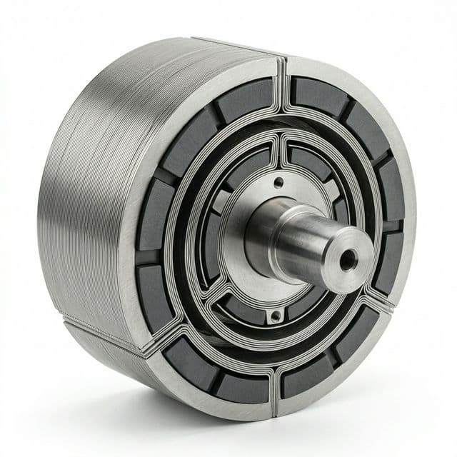
Ferrite Magnets in PMa-SynRM Rotors: Engineering Sizing, Flux-Barrier Tolerances, and Demagnetization Safeguards
Specify custom ferrite magnets for PMa-SynRM rotors: compare material data, check flux-barrier clearance and cold demagnetization, then prepare an OEM RFQ.
Mid-2026 OEM Magnet Sourcing: Impact of the Magnets Value Chain Support Act & Tariff Updates
Decision brief for OEM engineers and sourcing managers on the 2026 tariff updates and the newly introduced Magnets Value Chain Support Act, and what it means for custom ferrite magnet procurement.
Inquiry Email
Copy the email, or open your default email app to start an inquiry.