
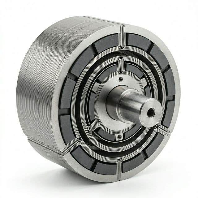
Ferrite Magnets in PMa-SynRM Rotors: Engineering Sizing, Flux-Barrier Tolerances, and Demagnetization Safeguards
Specify custom ferrite magnets for PMa-SynRM rotors: compare material data, check flux-barrier clearance and cold demagnetization, then prepare an OEM RFQ.
Custom ferrite magnets for PMa-SynRM rotors should be specified against three connected requirements: a temperature-dependent magnetic operating envelope, clearance inside the lamination pocket, and retention at maximum rotor speed. A room-temperature grade name alone cannot approve a rotor insert.
Permanent Magnet-Assisted Synchronous Reluctance Motors (PMa-SynRM) place hard ferrite inserts in rotor flux barriers to combine permanent-magnet excitation with reluctance torque. This guide helps motor designers, procurement managers, and quality engineers prepare a comparable RFQ and decide what needs validation before tooling release.
Reviewed: 26 October 2026. Scope: global OEM sourcing of sintered hard-ferrite rotor inserts. The decision matrix and worked clearance example below are engineering planning aids, not measured motor results or a released drawing. Bonded ferrite, complete motor certification, and application-specific current limits are outside this guide's scope.
Specifying custom ferrite rotor inserts?
Compare insert geometry, ground faces and magnetization options against your lamination drawing.
Explore SynRM Rotor Inserts
1. Operating Architecture: How Ferrite Assists a SynRM Rotor
A pure synchronous reluctance motor produces torque through the different magnetic reluctances of its rotor axes. Ferrite assistance adds excitation within the flux barriers. The resulting torque, power factor, and inverter demand depend on geometry and control; there is no universal percentage improvement or guaranteed IE4/IE5 class from the magnet material alone.
For a useful supplier brief, distinguish three interfaces:
- Magnetic: specify the insert's orientation and obtain material curves for the motor model.
- Mechanical: define the pocket envelope, minimum iron bridges, retention method, and overspeed condition.
- Drive: document the current trajectory and fault cases used to assess irreversible demagnetization.
This guide uses the SynRM convention in which the d-axis is the higher-permeance axis. Axis labels and current signs must match the motor designer's model; applying a negative d-axis current rule from a different PM motor convention can be misleading. A published ferrite-assisted external-rotor design illustrates why demagnetization assessment must follow the selected geometry and current loading.
Cross-Section Schematic: Flux Barriers & Ferrite Placement
The conceptual sector below identifies the features to mark on a drawing. It is not to scale, a validated pole layout, or a magnetic field solution. The header image is a product illustration, not evidence of tested motor efficiency.
2. Ferrite Grade Qualification Matrix: Coercivity, Remanence & Evidence
Treat intrinsic coercivity (Hcj) as a screening parameter alongside remanence (Br), not as a universal pass threshold. Neither a high Hcj nor a high Br independently establishes rotor performance. Labels such as Y30BH, Y33H, Y35, Y38H, and Ceramic 8B require the supplier's declared specification and test conditions; do not assume one-to-one GB/T, IEC, or MMPA equivalence.
IEC 60404-8-1:2015 covers principal magnetic properties and dimensional tolerances for magnetically hard materials. It does not qualify a particular motor. The following matrix is a buyer's acceptance framework, not a table of standardized grade substitutions.
Table 1: Six Inputs for Comparing Ferrite Rotor Grades
| Qualification input | What the RFQ must state | Evidence to request | Decision boundary |
|---|---|---|---|
| Remanence Br | Minimum/maximum in mT at the reference temperature | Material test report and measurement method | Compare usable flux in the rotor model, not Br alone |
| Intrinsic coercivity Hcj | Minimum in kA/m, with temperature stated | Guaranteed material limit and lot certificate | No grade-independent fault-current safety threshold |
| B-H and J-H curves | Lowest magnet temperature, reference point, hottest duty | Measured curves and recoil data for the proposed material | Check local operating points and irreversible loss |
| Maximum energy product (BH)max | Value in kJ/m³ and whether typical or guaranteed | Supplier specification with revision | Useful for material comparison; not a torque rating |
| Orientation and magnetization | Easy-axis direction, pole faces, delivery state | Marked drawing and agreed flux-test fixture | An identically sized insert can be magnetically incompatible |
| Production consistency | Sampling, acceptance limits and traceability | Lot data tied to drawing and material revisions | A prototype result does not establish production capability |
3. Cold Demagnetization: Curves Before Current Limits
The MMPA 0100-00 material specification, Table III-5 lists typical hard-ferrite temperature coefficients of about −0.2%/°C for Br and +0.2 to +0.5%/°C for intrinsic coercivity. These are design guidance, not acceptance limits or permission to extrapolate linearly over the full operating range.
Cooling can therefore reduce ferrite's coercivity even while remanence rises. Heating reduces remanence; that reversible effect must be separated from irreversible demagnetization. Torque loss cannot be inferred directly from a Br percentage in a reluctance-assisted machine.
OEM Safeguards for Cold-Climate Operation
- Request the actual temperature curves. For an outdoor program, −40°C, +20°C, and +120°C might be useful RFQ points; they are example conditions, not a universal standardized test set. Use your minimum magnet temperature and maximum duty temperature.
- Model local fields and faults. Check magnet corners as well as average values under startup, peak load, field weakening, and the defined short-circuit waveform. The external-rotor study evaluates demagnetization against current loading; its limits are specific to that machine.
- Validate controller safeguards. Derive current limits from the verified motor model and magnet-temperature estimate. A stator sensor crossing 0°C does not prove that a cold rotor is safe.
Ask the motor design owner to state an allowable irreversible flux-loss criterion and verification test. A room-temperature Hcj value cannot replace this sign-off.
4. Manufacturing & Sizing: A Flux-Barrier Clearance Example
Sintering and finish grinding are separate contributors to dimensional capability. Agree tolerances by dimension, pressing direction, and part geometry; a single percentage is not a reliable machining allowance. The pocket also varies with punching, burrs, stack alignment, and assembly conditions.
Worked Example: Ground Thickness Does Not Guarantee Fit
Illustrative assumptions only: a finished pocket thickness of 6.10 ±0.03 mm and a ferrite insert thickness of 6.00 ±0.04 mm. Assume these dimensions already represent the usable pocket and insert at inspection temperature.
- Minimum total clearance = (6.10 − 0.03) − (6.00 + 0.04) = 0.03 mm.
- Maximum total clearance = (6.10 + 0.03) − (6.00 − 0.04) = 0.17 mm.
- Nominal total clearance = 6.10 − 6.00 = 0.10 mm. It is not necessarily split equally between the two faces.
If the preliminary drawing requires 0.02–0.15 mm total clearance, this tolerance stack fails the upper limit by 0.02 mm. Tightening thickness alone may not be the cheapest fix: compare pocket capability, insert grinding yield, and the selected retention system. Do not release these example dimensions for manufacture.
Cost-Effective Tolerancing Strategy
- Critical pocket-facing surfaces: request a supplier capability review for precision grinding. A proposed ±0.03–0.05 mm thickness band must be accepted against the complete stack-up, rather than presented as an industry guarantee.
- Width and length: relax tolerances only after checking cavity ends, insertion direction, axial retention, magnetic leakage, and available adhesive clearance.
- Edges: identify which edges need a chamfer or radius and set an allowable chip envelope. A rectangular block has twelve edges; specify them on a drawing instead of asking for treatment of an undefined set of eight.
- Inspection: define datums, flatness, parallelism, burr allowance, and a functional insertion gauge. Validate bridge stresses and insertion force separately from dimensional clearance.
Use the mass-production ferrite tolerance guide to prepare the drawing review before requesting production pricing.
5. Cavity Retention & Assembly Methods
Retention must be qualified against rotor overspeed, thermal cycling, vibration, and the intended service life. The comparison below identifies questions for the design review; it does not assign certified speed ranges, cycle times, or recycling compliance.
Table 2: Rotor Magnet Retention Trade-Offs
| Retention method | Assembly consideration | Cost driver | Qualification question | Disassembly consideration |
|---|---|---|---|---|
| Lamination tabs or mechanical features | Control insertion force and ceramic contact stress | Stamping tooling and feature consistency | Can the features retain the insert without chipping or bridge damage? | Check whether extraction damages the stack |
| Structural adhesive or potting | Control bond-line thickness, cleanliness and cure | Dispensing, material and cure time | Does the bond survive the specified temperature, fluids and cycling? | Debonding depends on adhesive chemistry; no universal release temperature |
| Polymer encapsulation | Account for molding pressure and thermal expansion | Mold tooling and process yield | Do molding loads and polymer creep preserve retention? | Separating polymer, steel and ferrite may be difficult |
| Spring clips or compliant shims | Control preload, contact area and insertion sequence | Clip parts and assembly labor | Are fatigue, fretting and local contact stresses acceptable? | May permit removal if access and design allow |
6. Sourcing & Economics: Compare Cost per Accepted Rotor
Obtain dated quotations at the same annual volume, drawing revision, delivery state, currency, and Incoterm. This guide provides no current market price benchmark. Compare total landed cost per accepted rotor, rather than assuming a fixed saving from magnet price per kilogram.
Include insert quantity and mass, grinding yield, edge finishing, inspection, packaging, freight, tooling amortization, retention material, assembly time, and scrap. Record magnet mass and cost separately so a heavier ferrite design does not inherit an NdFeB mass assumption.
Rotor Manufacturing Trade-Offs
- Envelope and stack length: request comparable motor designs at the same torque-speed duty, thermal limit, DC bus, and inverter current. Lower Br does not prescribe a fixed stack-length increase in a reluctance-assisted machine.
- Tooling and assembly: compare bridge geometry, stamping capability, insertion yield, and retention validation before accepting a magnet-only cost reduction.
- Supply resilience: ferrite can remove rare-earth dependence from the magnet bill of materials. Supplier concentration, energy costs, logistics, and applicable trade rules still need review.
7. OEM Procurement & Engineering RFQ Checklist
Use these eight gates to identify missing information before tooling release. Record the responsible supplier or motor-design owner for each open item.
- Gate 1 — Pocket interface: attach a revision-controlled drawing with datums, all insert dimensions, tolerance stack-up, fit, and functional gauge requirements.
- Gate 2 — Temperature curves: request measured B-H/J-H and recoil data at the agreed magnet temperatures; assign the motor owner to approve the local demagnetization margin.
- Gate 3 — Material acceptance: state guaranteed Br and Hcj limits, reference temperature, test method, sampling, and the supplier's exact material designation.
- Gate 4 — Edge geometry: mark chamfers/radii and chip limits on the drawing; verify representative parts through the actual insertion sequence.
- Gate 5 — Flux consistency: agree a total-flux or fixture-based measurement, magnetization state, measurement temperature, and acceptance window. Surface gauss alone is geometry dependent.
- Gate 6 — Cleanliness: agree loose-particle and crack criteria, collection/inspection methods, and packaging controls. Any numerical debris limit must be a customer requirement with a reproducible test.
- Gate 7 — Packaging: define tray or tube geometry, polarity/orientation marking, handling protection, and robot-pick compatibility; state whether magnetization occurs before or after assembly.
- Gate 8 — Production approval: agree first-article records, capability studies, traceability, change notification, and PPAP level where the customer requires it. Define capability targets contractually.
8. Frequently Asked Questions (FAQ)
Executive Sourcing Recommendation
Qualify custom ferrite inserts as part of the rotor and drive design, using traceable material data and a controlled pocket interface.
Recommended Action
Before tooling release, close the drawing stack-up, approve temperature-dependent demagnetization analysis, and agree production inspection and retention validation.
Caution
The numerical clearance example is illustrative. Neither a grade name nor room-temperature Hcj establishes motor safety or an IE efficiency class.
Ready for a drawing review? Send your pocket drawing, temperature range, current/fault envelope, magnetization direction, retention concept, and annual volume through the SynRM rotor insert product enquiry to request a feasibility review and comparable quotation.
Evidence and Applicability Notes
Last reviewed: 2026-10-26
Sources Used
- IEC 60404-8-1:2015: material properties and dimensional-tolerance scope; publication record, not a motor certificate.
- MMPA 0100-00: Section III, especially Table III-5; historical material guidance, not a supplier-specific guarantee.
- Applied Sciences 2021, 11(7), 3102: a specific ferrite-assisted external-rotor design; see full reference below.
Method
- Compared published material guidance with the evidence a rotor-insert RFQ needs.
- Calculated a worst-case thickness clearance using explicitly hypothetical pocket and magnet dimensions.
- Prepared qualitative retention and sourcing decisions; no factory audit, motor test or customer case study is claimed.
Applicability Boundary
- Applies to sintered hard-ferrite insert sourcing; material grade aliases require explicit supplier confirmation.
- Motor sizing, local demagnetization and bridge stress require project-specific electromagnetic and mechanical validation.
- Cost, production capability, certification and recovery rates require current project evidence.
Related Internal Guides
- Ferrite Rotors for SynRM Motors Product Catalog
- Anisotropic Ferrite vs Neodymium: 2026 Engineering Decision Guide
- Ferrite Magnet Tolerance Guide for Mass Production
- Low-Temperature Demagnetization in Ferrite Magnets: An OEM Sourcing Guide
- Visual Acceptance Standards for Ferrite Magnets: Chipping and Cracks
Authoritative Standards & References
Sources reviewed 26 October 2026. Historical specifications and a single motor study support the stated principles, not universal grade equivalence or production guarantees.
- IEC 60404-8-1:2015 — Magnetic materials: specifications for magnetically hard materials. Publisher's scope record; consult the contractual edition for acceptance requirements.
- MMPA Standard No. 0100-00 — Standard Specifications for Permanent Magnet Materials. Section III and Table III-5, printed pages 10–14; legacy ceramic-material and temperature guidance.
- Design of External Rotor Ferrite-Assisted Synchronous Reluctance Motor for High Power Density. Applied Sciences 2021, 11(7), 3102; DOI: 10.3390/app11073102. Design-specific evidence, not a test of FerriteCustom products.
Author

Categories
More Posts
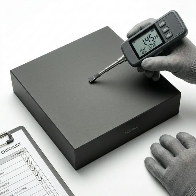
OEM Ferrite Supplier Audit Checklist
A buyer-side audit checklist covering process control, quality systems, and delivery reliability for ferrite magnet suppliers.

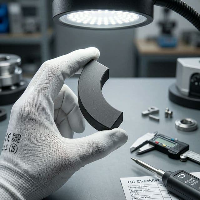
Ferrite RFQ Checklist for OEM Buyers
A practical RFQ checklist that helps purchasing and engineering teams get faster, comparable ferrite magnet quotations.
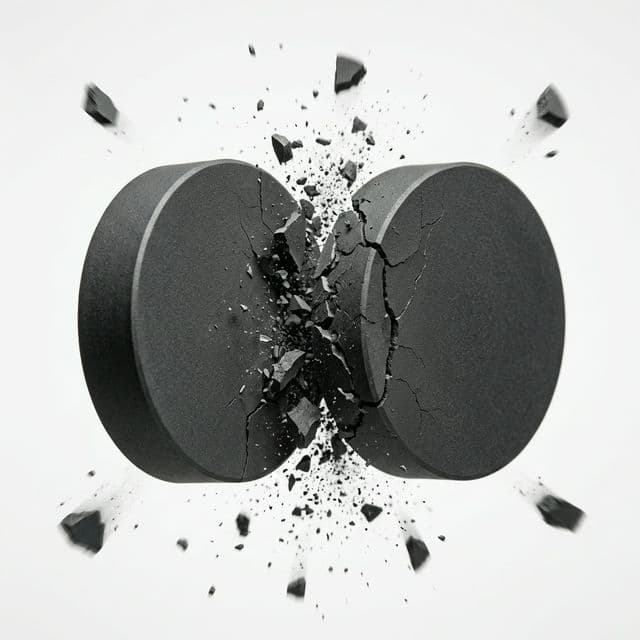
Ferrite vs Neodymium Magnets: B2B Selection Guide
A procurement-focused comparison of ferrite and neodymium magnets across cost, thermal stability, supply risk, and lifecycle fit.
Inquiry Email
Copy the email, or open your default email app to start an inquiry.