
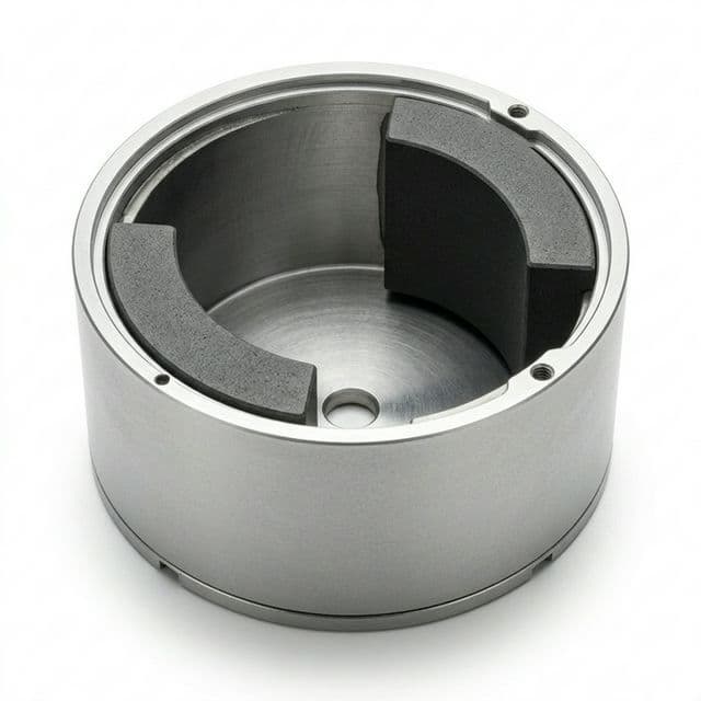
Ferrite Arc Segments in Motor Stators: Engineering Sizing, Camber Tolerances, and Stator Assembly Fit
Size custom ferrite arc segments for motor stators: check camber, air-gap stacks, grinding scope, and RFQ requirements. Explore options for your OEM drawing.
Custom ferrite arc segments (tile magnets) provide the stationary permanent magnet field in brushed permanent magnet DC (PMDC) motors. For a buyer sizing these parts, the first decisions are the housing seating surface, installed inner profile, magnetic orientation, and required clearance to the rotating armature. Specify these interfaces before choosing which surfaces need grinding.
Architecture check: In a conventional BLDC motor, permanent magnets are on the rotor and the stator carries windings. This article addresses housing-mounted PMDC stator arcs; its assembly stack must not be applied directly to BLDC rotor magnets, which need separate retention and centrifugal-load analysis.
Sintered ferrite is brittle. Shrinkage and profile variation can change how a tile seats in its housing, alter the adhesive bond line, and consume the available air gap. Tightening every radius and thickness independently can also introduce conflicting acceptance requirements. This guide connects those drawing decisions to inspection and RFQ requirements for motor designers, sourcing managers, and supplier quality engineers.
Reviewed: 28 October 2026. Scope: Global OEM sourcing of sintered anisotropic strontium ferrite arcs for PMDC stator housings. Bonded ferrite, soft ferrite cores, and rotor-mounted magnets are outside this assembly example. Numerical examples below are illustrative engineering assumptions, not production measurements or guaranteed supplier capabilities.
Sourcing custom ferrite stator arc segments?
Prepare the housing envelope, armature drawing, temperature range, and annual volume for a drawing review.
Explore Ferrite Arc Segments
1. Anatomy of a Ferrite Arc Segment: Geometric Definitions & Drawing Traps
For a concentric circular arc, define the following parameters and the measurement section on the drawing:
- Outer radius (Ro): The convex seating surface facing the steel housing or yoke.
- Inner radius (Ri): The concave surface facing the rotating armature.
- Radial thickness (T): For concentric surfaces,
T = Ro − Ri. An eccentric profile requires a thickness map instead. - Inner chord (Wi) and outer chord (Wo): Straight distances between the tips on the respective surfaces. A single unspecified chord width is ambiguous.
- Inner sagitta (Si): Nominal height of the inner arc above its own chord:
Si = Ri − sqrt(Ri² − (Wi/2)²)for a minor arc. Do not substitute the outer chord into this equation. - Subtended angle (θ): Mechanical span of the arc;
Wi = 2 × Ri × sin(θ/2)andWo = 2 × Ro × sin(θ/2). - Axial length (L): Magnet length parallel to the shaft.
- Chamfers and edge radii: Drawing-defined edge breaks for handling, seating, and orientation.
Sagitta is nominal geometry; camber is departure from the specified profile. For example, an inner radius of 42.88 mm and an inner chord of 60.00 mm give a nominal sagitta of approximately 12.24 mm. A measured sagitta difference is meaningful only with the same chord endpoints, support conditions, and reference profile.
Avoid Redundant Independent Tolerances
Ro, Ri, and T are coupled, as are radius, chord, and angle. Independent tolerances can be valid, but their combinations must be compatible. Ask the supplier to flag combinations that cannot be inspected or produced consistently; grinding every surface is not an automatic consequence or a universal remedy.
Choose functional datum features from the installed seating and locating interfaces. Then choose the controlling dimensions/profile requirements and identify derived reference dimensions (REF). A datum is a reference feature, not a quota of three dimensions: axial length, positioning, and edge conditions still need requirements where function depends on them.
2. Anisotropic Pressing & Sintering: What the Buyer Must Confirm
Wet pressing can align ferrite particles in a magnetic field before sintering. Dry processing can also produce anisotropic material; the process name alone does not establish magnetic performance. Ask the supplier which process, grade, and orientation its quotation covers.
A useful process review follows five steps:
- Powder and slurry preparation: Confirm material traceability and the supplier's process controls.
- Field-assisted compacting: Specify radial or parallel orientation relative to the part drawing. Press orientation and final magnetization are separate requirements.
- Drying and sintering: Let the supplier validate its firing cycle, shrinkage compensation, and cavity tooling. Fixed slurry percentages, pressing pressures, or shrinkage factors cannot be inferred from the finished geometry.
- Profile correction and cleaning: Identify the ground surfaces and how dust and coolant residues will be removed.
- Final verification: Check free-part geometry, installed seating, and the agreed magnetic test after the intended magnetization sequence.
Camber may reflect pressing density, tooling, drying, or sintering variation. Require first-article profile measurements across cavities rather than assigning a single universal distortion mechanism.
3. Engineering Stator Assembly Cross-Section Schematic
The diagram identifies the interfaces in a two-pole PMDC stator assembly. It is schematic and not to scale; the nominal labels match the worked example in Section 6. Colors identify the two pole pieces, not a measured field distribution. The header product image illustrates housing-mounted ferrite arcs and is not evidence of a tested assembly.
4. Motor Stator Ferrite Grade Selection Matrix
Remanence (Br), intrinsic coercivity (Hcj), the magnetic load line, and armature reaction jointly affect the result. A grade label alone does not approve stall torque or demagnetization margin.
IEC 60404-8-1:2023 addresses permanent magnet material properties and dimensional tolerances. Use the supplier's identified grade specification and agreed test conditions; Chinese Y-series names, IEC codes, and MMPA Ceramic grades are not automatic one-to-one substitutes.
| Engineering question | Request in the RFQ | Decision boundary |
|---|---|---|
| Required air-gap flux / back-EMF | Br range and second-quadrant curves for the quoted grade | Higher Br alone does not establish motor torque or efficiency. |
| Cold-start or locked-rotor duty | Temperature-specific demagnetization curves and maximum reverse-field/current condition | Evaluate the operating point relative to the knee, then test the assembled motor. |
| Hot continuous operation | Curves at the maximum magnet temperature and allowable irreversible flux loss | Include winding heat, adhesive, housing, and duty cycle. |
| Magnetic orientation | Radial or parallel orientation on the drawing, with pole-face identification | These orientations are not interchangeable in the same simulation. |
| Cross-supplier grade substitution | Original specification, proposed grade data, and comparison at identical conditions | Similar grade names do not establish equivalence. |
| Incoming magnetic acceptance | Defined magnetization state, test fixture, flux limits, and lot sampling | A material coupon result alone does not establish installed arc performance. |
Temperature Behavior and the Cold-Start Check
Hard ferrite generally has decreasing Br and increasing Hcj as temperature rises. The MMPA reference, Table III-5, gives typical coefficients, not grade-specific release limits.
For arithmetic illustration only, assume Hcj at 20°C is 220 kA/m and a constant coefficient of +0.25%/°C is valid down to −40°C:
Hcj(−40°C) ≈ 220 × [1 + 0.0025 × (−40 − 20)] = 187 kA/mThis estimate cannot locate the demagnetization knee or approve a motor. Request the actual grade curves over the application temperature range and evaluate reverse armature field at the maximum permitted stall current. There is no universal room-temperature Hcj threshold that makes every cold-start design acceptable.
5. Dimensional Tolerance Architecture: As-Sintered vs. Diamond-Ground
Grinding can tighten a selected surface, but the installed profile depends on the seating datum, thickness variation, housing shape, and adhesive fixture. Grinding Ri while leaving Ro as-sintered does not by itself control the final assembled air gap.
The following RFQ planning examples are proposed targets, not verified production capabilities or standard tolerances. Units are millimeters unless stated otherwise. Approve each requirement with the supplier against the actual size and geometry.
| Feature | As-sintered RFQ approach | Example ground / controlled target | Inspection and assembly question |
|---|---|---|---|
| Outer profile (Ro) | Request the measured seating envelope | ±0.05 radius, if a radius tolerance is suitable | Will a functional housing gauge confirm seating without forcing the tile? |
| Inner profile (Ri) | Request the free-part profile range | ±0.04 radius, relative to agreed datums | Does the installed profile still meet the rotor clearance requirement? |
| Radial thickness (T) | Example stack allowance: ±0.20 | Example stack allowance: ±0.03 | Can the quoted process hold thickness at the agreed crown and tip locations? |
| Specified chord (Wi or Wo) | Request cavity-specific variation | ±0.08 on the identified chord | Do pole spacing and any retaining clips accommodate the full range? |
| Axial length (L) | Match the end-location and overlap budget | ±0.05 if required by that budget | Is end-face grinding needed for assembly location? |
| Camber / profile departure | Establish a free-part and seated-profile baseline | Example maximum profile departure: 0.05 | Define support points and gauge force; do not label a static arc measurement as rotational TIR. |
| Chamfers and edge radii | Agree molded or finished edge conditions | Dimension from feeder, contact, and magnetic requirements | Does the edge avoid chipping without removing required pole-face material? |
Compare these requirements with the ferrite tolerance guide. For a drawing review, explore the stator assembly options with your seating datum and grinding scope identified.
6. Stator Assembly Fit & Air-Gap Tolerance Stack-Up: Worked Example
This is a hypothetical radial stack, not a measured automotive program. All deviations below are radial contributions in millimeters. Convert diameter tolerances to radial values before combining them; convert runout measurements according to their defined datum and measurement method.
Nominal Design Inputs
- Housing inside radius (Rcan): 50.00 mm
- Radial adhesive bond line (tglue): 0.12 mm
- Magnet outer radius (Ro): 49.88 mm
- Magnet thickness (T): 7.00 mm
- Magnet inner radius (Ri): 42.88 mm
- Rotor outside radius (Rrotor): 42.38 mm
g_nominal = Rcan − tglue − T − Rrotor
          = 50.00 − 0.12 − 7.00 − 42.38 = 0.50 mm
This model assumes controlled concentric seating and no unmodeled local camber. Ro and Ri are derived checks in this stack, not extra independent contributors.
Worst-Case Minimum Gap
| Independent contribution | Adverse radial deviation | Assumption |
|---|---|---|
| Housing inside radius | −0.05 mm | A radius tolerance, not an ID diameter tolerance |
| Bond line | +0.06 mm | Maximum glue thickness is 0.18 mm |
| Magnet thickness, Case A | +0.20 mm | Illustrative as-sintered allowance |
| Magnet thickness, Case B | +0.03 mm | Illustrative tighter thickness allowance; process must be demonstrated |
| Rotor envelope and assembly eccentricity combined | +0.08 mm | Already expressed as a one-sided radial contribution; avoid counting it twice |
Case A: g_min = 0.50 − 0.05 − 0.06 − 0.20 − 0.08 = 0.11 mm
Case B: g_min = 0.50 − 0.05 − 0.06 − 0.03 − 0.08 = 0.28 mm
Improvement in the modeled minimum gap: 0.17 mm
Case B leaves more modeled clearance, but neither result establishes safe operation. Add thermal growth, shaft/bearing displacement, dynamic rotor deflection, and local profile variation that are absent from this simplified stack. Set the required residual clearance from the motor design and validation plan; 0.25 mm is not a universal safe threshold. A ground inner surface only earns the Case B allowance if thickness and installed location are demonstrated.
7. Stator Magnet Retention & Structural Assembly Methods
Choose retention for the complete assembly, not from the ceramic's nominal temperature resistance. The following methods require project-specific qualification; no generic temperature or bond-strength rating applies to every material combination.
| Retention method | Main reason to consider it | What must be qualified |
|---|---|---|
| Structural adhesive | Distributes support between ferrite and housing | Actual adhesive data, surface preparation, cure, bond-line range, fluid exposure, and thermal cycling |
| Spring retaining clips | Provides mechanical retention without relying solely on cure | Contact stress, clip preload, tip geometry, fretting, and housing tolerances |
| Plastic cage / end rings | Locates parts and can simplify assembly handling | Polymer creep, moisture, operating temperature, and loss of preload |
| Overmolding | Integrates location and protection into a molded assembly | Ferrite cracking, molding loads, shrinkage, and thermal mismatch |
Check retention after vibration and thermal exposure using the actual housing finish and magnet cleaning process. Ferrite must not be treated as a ductile structural spring.
8. Automated Assembly DFM: Orientation & Chipping Mitigation
- Key geometry to a verified pole map: An asymmetric chamfer can orient a part only if its relationship to magnetization is controlled. Axial reversal of a uniformly magnetized radial arc does not automatically reverse its inner-face polarity. Use pole testing or controlled post-assembly magnetization as appropriate.
- Define edge acceptance: Choose chamfers, tip lands, and radii from the feeder and seating design. Avoid imposing one universal bevel size on every arc. See ferrite edge finishing options.
- Control assembly force: Support the tile and bound insertion or clip loads. Do not force an out-of-profile tile into the housing.
- Control dust and handling: Agree a cleaning process compatible with the adhesive, dryness criteria, tray layout, and measurable loose-particle acceptance. Ceramic swarf is not inherently ferromagnetic; residual coolant and trapped particles can still compromise the bond or motor clearance.
9. Sourcing Economics: Tooling Amortization vs. Piece Price
Request separate quotes for existing-tool parts, selective grinding, and a custom die. Each quote should state tooling ownership, cavity count, annual-volume assumption, grinding scope, first-article schedule, inspection, and packaging. Published universal tooling prices, yields, and cycle-time multipliers cannot replace that quotation.
Illustrative break-even calculation: Assume a new tool adds US$6,000 and saves US$0.03 per accepted part relative to an existing-tool option. With equal inspection, scrap, freight, and financing costs, 6,000 / 0.03 = 200,000 accepted parts is the simple break-even quantity. These are hypothetical commercial inputs, not a FerriteCustom price offer.
A lower quoted piece price may not be the lower delivered cost if it requires extra sorting, rework, or an assembly change. Evaluate alternatives against the same installed-fit and magnetic acceptance requirements.
10. OEM Procurement & Engineering RFQ Checklist
- Gate 1 — Geometry and datums: Identify the housing seating datum, chord surface, profile limits, axial length, and compatible derived dimensions.
- Gate 2 — Magnetic requirements: Supply grade specification, temperature range, radial/parallel orientation, magnetization state, pole map, and stall-current boundary.
- Gate 3 — Grinding scope: Mark ground and as-sintered surfaces individually; request evidence for the proposed thickness and profile limits.
- Gate 4 — Camber inspection: Agree chord endpoints, support points, contact force, reference master, measurement uncertainty, and free-part versus seated acceptance.
- Gate 5 — Assembly orientation: Link any physical key or pole marking to the specified magnetization and feeder inspection.
- Gate 6 — Defect acceptance: Agree chip/crack limits by location, loose-particle rules, defect classes, and the sampling plan. An AQL is a sampling parameter, not a permissible chip size. Use the visual acceptance guide to prepare signed sample boards.
- Gate 7 — Packaging and cleanliness: Define magnetized or unmagnetized delivery, separation, cleanliness, and transport requirements.
- Gate 8 — Production approval: Agree first-article quantities by cavity, measurement-system review, capability-study method, material batch traceability, and any customer-required PPAP level. Ferrite is a ceramic powder process; ask for powder/sintering batch records rather than a metal melt-lot certificate.
11. Frequently Asked Questions (FAQ)
Should we grind the inner radius or the outer radius?
Choose from the installed datum chain. The inner surface bounds rotor clearance, while the outer surface controls seating and adhesive space. Selective grinding can reduce cost, but an inner-radius tolerance alone cannot compensate for uncontrolled outer-profile seating or bond thickness.
How should incoming inspection measure camber?
Define whether the requirement is a sagitta deviation, local profile departure, or seated fit. Specify chord endpoints, support points, gauge force, and a calibrated master. A two-support and center-probe fixture can screen sagitta; it does not reconstruct the complete profile. Use an agreed profile scan or functional housing gauge where needed.
Can ferrite arc segments be shipped pre-magnetized?
Yes, if the agreed pole map, packaging, handling, and incoming flux test support that route. Unmagnetized delivery requires an assembly magnetizing fixture proven to reach the intended magnetic state. Choose the sequence with the assembly plant before ordering parts.
What causes bond failures between ferrite arcs and steel housings?
Possible contributors include contamination, incomplete cure, inappropriate bond thickness, profile mismatch, and thermal or fluid exposure. Qualify the actual adhesive and surface preparation on representative parts. No adhesive chemistry or generic strength value guarantees every stator assembly.
Why can a motor have cogging torque despite precision-ground magnets?
Cogging depends on the interaction between slotting and magnetic field distribution, not only dimensional accuracy. Pole arc, orientation, eccentric profiles, and rotor skew can change the result. Evaluate candidate changes by electromagnetic analysis and motor testing rather than applying a universal skew angle.
Does wet pressing always outperform dry pressing?
The quoted grade and orientation data decide the comparison. Both wet and dry routes can produce anisotropic ferrite. Ask for the actual demagnetization curves and dimensional capability; neither the process label nor an assumed energy-product ceiling is an acceptance specification. See the wet versus dry pressing guide.
Visual Decision Aids
Decision Snapshot
| Program requirement | Drawing / sourcing action | Release boundary |
|---|---|---|
| Tight radial clearance | Quote selective grinding against the installed datum chain | Demonstrate the full clearance stack, including dynamic effects. |
| Sub-zero stall duty | Obtain cold demagnetization curves and define the reverse-field/current condition | Validate irreversible flux loss on the motor; see the low-temperature guide. |
| Automated feeding | Agree edge breaks, pole identification, cleanliness, and trays | Prove feeder orientation and ceramic handling on a pilot lot. |
| Cost-sensitive production | Compare existing tooling, selective grinding, and custom tooling | Apply identical installed-fit and magnetic acceptance limits to each quote. |
Engineering and Sourcing Recommendation
Start with the installed datum chain and magnetic duty, then negotiate the process and inspection plan.
Recommended Action
Send the supplier a dimensioned stator drawing, radial clearance budget, orientation and pole map, temperature range, and annual volume. Release tooling after the proposed geometry and magnetic acceptance methods are agreed.
Caution
Illustrative dimensions and arithmetic cannot establish supplier capability, grade equivalence, adhesive life, or safe operating clearance.
For a drawing discussion, review the Ferrite Arc Segments product options and Motor Stator Assembly options. Prepare your 2D print, housing and rotor envelopes, temperature range, magnetization requirements, and estimated annual volume for the inquiry.
Evidence and Applicability Notes
Evidence and Applicability Notes
Last reviewed: 2026-10-28
Sources Used
- IEC 60404-8-1:2023: permanent magnet material specification scope; official catalogue record.
- IEC 60404-5:2015: magnetic measurement methods; official catalogue record.
- MMPA 0100-00: Sections I and III; legacy guidance on ceramic magnets and functional arc gauging.
Method
- Defined concentric-arc chord and sagitta equations and an explicitly radial worst-case clearance model.
- Calculated the stated hypothetical inputs directly; no motor testing, production capability study, or customer case study is claimed.
- Separated source-backed material and measurement scope from proposed RFQ targets and supplier qualification requirements.
Applicability Boundary
- Applies to housing-mounted PMDC stator arcs; conventional BLDC rotor magnets require a separate retention assessment.
- The example omits thermal growth and dynamic deflection; motor clearance, magnetic margin, and retention require project validation.
- IEC catalogue abstracts verify standard identity and scope, not the full paid clauses. MMPA guidance does not establish a modern supplier capability guarantee.
Related Internal Guides
- Ferrite Arc Segments Product Options
- Ferrite Motor Stators and Assembly Options
- Ferrite Edge Chamfering and Chipping Prevention
- Visual Acceptance Standards: Edge Chipping and Cracks
- Ferrite Magnet Tolerance Guide for Mass Production
- Low-Temperature Demagnetization in Ferrite Magnets
- Wet Press vs Dry Press Ferrite
External References
These references support material-specification and measurement context. They do not establish this article's illustrative machining targets, prices, or motor release criteria. Agree the applicable standard edition and acceptance method in the purchase specification.
- IEC 60404-8-1:2023 — Permanent magnet material specifications: replaces the 2015 edition cited in the original draft.
- IEC 60404-5:2015 — Measurement of permanent magnet properties: use the identified method and test conditions for material characterization.
- MMPA Standard No. 0100-00 — Permanent Magnet Materials: legacy guidance; distinguish typical material values from contractual acceptance requirements.
Author

Categories
More Posts
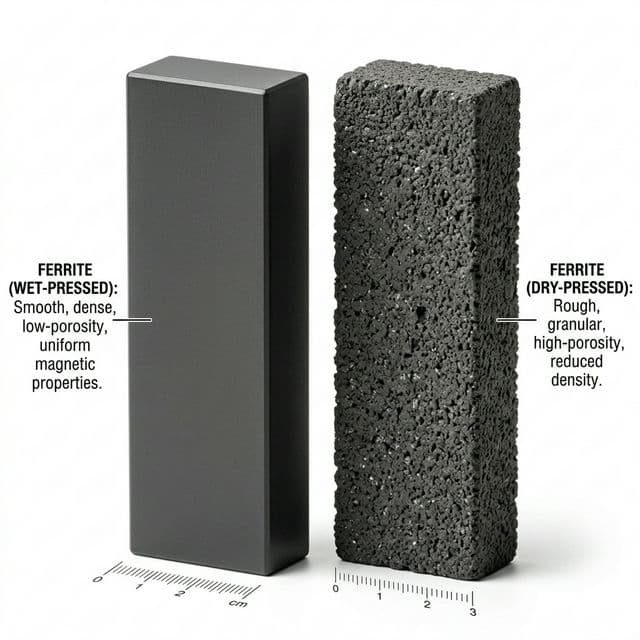
Wet Press vs Dry Press Ferrite: Process Selection for OEM Programs
How to choose wet-pressed or dry-pressed ferrite routes based on geometry, consistency targets, and total manufacturing economics.

CEN/TS 18263:2026 Permanent Magnet Labeling: A Sourcing Guide for Ferrite Buyers
Learn how CEN/TS 18263:2026 affects custom ferrite magnet RFQs, supplier audits, labeling data, and EU DPP readiness before 2026 sourcing programs launch.
Ferrite vs Neodymium Magnets: B2B Selection Guide
A procurement-focused comparison of ferrite and neodymium magnets across cost, thermal stability, supply risk, and lifecycle fit.
Inquiry Email
Copy the email, or open your default email app to start an inquiry.