
Radial Multipole Ferrite Rings for BLDC Motors: Sizing, Pole Transitions, and Sourcing Controls
Specify custom radial multipole ferrite rings for BLDC motors: calculate neutral zones, evaluate wet vs dry pressing, set runout TIR, and secure tooling RFQs.
Radial multipole ferrite rings provide the rotor magnetic field for electronically commutated (EC) brushless DC (BLDC) motors, including electric coolant pumps and hydronic heating circulators; they also serve as targets for magnetic rotary encoders. A monolithic cylindrical ceramic ring carries alternating radial North and South poles around its circumference. Segmented arcs remain another option for both brushed and brushless motor architectures.
Specifying a custom multipole ferrite ring requires balancing magnetic orientation physics, mechanical shaft retention, and air-gap harmonic distortion. If an engineering drawing specifies pole count without accounting for the physical width of the magnetic neutral transition zone, the motor may suffer severe torque ripple, acoustic resonance, or fail to achieve its rated back-electromotive force (back-EMF). Conversely, over-constraining concentricity and inner bore tolerances without identifying functional datum features drives excessive diamond grinding costs and unnecessary scrap.
This guide helps motor design engineers, procurement specialists, and supplier quality managers define the technical boundaries, drawing requirements, and verification protocols needed before releasing custom radial multipole ferrite tooling.
Reviewed: 1 November 2026. Scope: Global OEM sourcing of sintered anisotropic and isotropic strontium ferrite multipole rings for brushless permanent magnet motors and magnetic encoders. Bonded rings are addressed for architectural comparison. Numerical examples and acceptance targets are illustrative engineering proposals, not measured production capability, motor test results, supplier quotations, or limits prescribed by the cited standards. Confirm grade data and pilot-lot results for your geometry before release.
Sourcing custom radial multipole ferrite rings?
Submit your pole count, air-gap envelope, target flux waveform, and annual volume for custom tooling evaluation.
Explore Multipole Rings
1. Rotor Architecture: Monolithic Multipole vs Segmented Arcs vs Bonded Rings
When designing a permanent magnet rotor for a BLDC motor or pump, engineering teams evaluate three primary permanent magnet configurations:
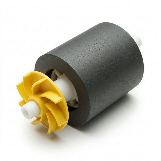
- Monolithic Sintered Ferrite Ring: A single-piece cylindrical ceramic sleeve with a specified radial pole pattern. It removes individual segment placement and its angular tolerance stack. It remains brittle: allowable speed depends on ring dimensions, flaws, retention, temperature, and overspeed qualification; there is no architecture-wide RPM rating.
- Segmented Arc Assembly: Discrete ferrite tiles bonded around a rotor core. Segment gaps and placement affect the magnetic waveform, but their effect on cogging depends on the slot/pole combination and complete motor design. For stator applications, see our companion guide on ferrite arc segments in motor stators.
- Bonded Injection-Molded Rings: Ferrite powder compounded into a thermoplastic matrix such as PPS or polyamide. They permit net-shape features and insert molding. Binder content, powder orientation, and molding conditions determine magnetic performance and tolerances; request the actual compound datasheet rather than assuming a fixed energy product.
Product illustration for assembly context; it does not establish material grade, pole pattern, or tested pump performance.
The selection between monolithic sintered rings and alternative architectures depends on annual volume, operating temperature, available air-gap volume, and target assembly automation:
| Architecture | Magnetic Selection | Tooling / Assembly Trade-Off | Evidence Needed Before Release |
|---|---|---|---|
| Anisotropic Wet-Pressed Ring | Oriented grade; verify the easy-axis pattern | Orientation tooling and magnetizing fixture must match | Grade curves, orientation map, pilot scan |
| Isotropic Dry-Pressed Ring | Lower magnetic output for a comparable envelope | Blank can support different qualified pole fixtures | Available flux at the working gap |
| Segmented Sintered Arcs | Grade and segment orientation chosen separately | Additional segment placement and retention steps | Gap/angle stack, bond validation, assembled scan |
| Bonded Injection-Molded (PPS) | Compound-dependent output and temperature limits | Insert molding can integrate retention features | Compound datasheet, shrinkage and fluid-aging tests |
| Bonded Compression-Molded | Powder loading and orientation determine output | Separate attachment and any finishing operations | Grade data, dimensions and retention testing |
| Segmented Halbach Array | Can concentrate flux on one side; geometry-dependent | Multiple magnetization directions complicate assembly | Field model, orientation verification and retention |
Sintered ferrite is useful in wet-rotor designs, but material choice alone does not qualify immersion service. Test the complete ring, shaft, adhesive, and polymer assembly in the specified coolant chemistry, temperature, and pressure cycle. Balance quality must be verified on the assembled rotor under ISO 21940-11; it cannot be inferred from the magnet architecture.
2. Magnetic Orientation Physics: Radial Anisotropic vs Isotropic Tooling
A common procurement pitfall is requesting an "anisotropic multipole ring" without specifying its orientation pattern. Ferrite particles possess a preferred crystallographic magnetic axis. Field-assisted pressing aligns these axes; wet pressing is one route, while dry pressing can also be field-oriented. Supplier labels such as Y30BH, Y33, or Y35 are not a substitute for an agreed specification. Request remanence, intrinsic coercivity, energy product, test temperature, and any documented cross-reference to IEC 60404-8-1:2023.
The Radial Pressing Dilemma
Ask the supplier to distinguish the following orientation routes and identify which tooling changes with pole count:
- Polar-Oriented Anisotropic Tooling: The pressing field creates an easy-axis pattern optimized for a particular multipole layout. A different pole count may require revised orientation tooling as well as a new magnetizing fixture; obtain a tooling compatibility statement before changing the design.
- Continuous Radial Anisotropic Tooling: Easy axes follow the radial direction around the circumference. Different alternating-pole patterns may be feasible after pressing, subject to supplier capability and waveform qualification. Radial orientation does not guarantee arbitrary pole counts or uniform flux.
- Isotropic Compaction with Multipole Post-Magnetization: No alignment field is applied, leaving particle axes randomly oriented. Different magnetizing fixtures can produce different pole patterns in a common blank, within geometry and field limits. Isotropic material generally has lower remanence and energy product than comparable oriented material; remanence and energy-product ratios are different quantities and must come from grade data.
Where the envelope demands more air-gap flux, evaluate an anisotropic route first. Select isotropic material when its measured output meets the torque or sensing requirement and its tooling flexibility is useful. See our comparison on wet press vs dry press ferrite manufacturing.
3. Physics of the Pole Transition Zone and Harmonic Shaping
In an ideal theoretical model, a multipole rotor exhibits instantaneous polarity reversal at the boundary between adjacent North and South poles. In real-world ceramic manufacturing, magnetic flux lines cannot switch direction infinitely fast. The physical space between adjacent magnetic poles is known as the pole transition zone or magnetic neutral zone.
Calculating Neutral Zone Limits and Pole Pitch
The mechanical pole pitch angle θp is determined by the total pole count P:
θp = 360° / P
For an 8-pole rotor:
θp = 360° / 8 = 45.0°
Along the outer circumference of a ring with outer radius Ro, the mechanical pole pitch arc length wp is:
wp = (2 × π × Ro) / P
The measured radial field B_rad reverses sign at each boundary. A zero crossing is a point; a transition width requires an agreed threshold, such as the interval from +10% to -10% of a reference peak. Specify that threshold, probe standoff, axial track, and temperature. Here B_rad denotes the scanned field; Br in material datasheets denotes remanence. Fixture geometry, material orientation, and measurement gap all affect the observed transition:
- Illustrative transition width (wtrans): 2.2 mm along the outer circumference, assumed for the calculation below; not a universal fixture capability.
- Angular transition width (Δθtrans):
Δθtrans = (wtrans / Ro) × (180° / π).
If an engineering team specifies an 8-pole rotor on a ring with outer radius Ro = 25 mm (outer diameter 50 mm):
wp = (π × 50 mm) / 8 = 19.63 mm
Assuming a measured transition width wtrans = 2.2 mm under the agreed threshold definition, the angular transition zone consumes:
Δθtrans = (2.2 mm / 25 mm) × (180° / π) = 5.04°
For a simplified flat-top pole model, the arc outside the transition interval is:
θmag = θp − Δθtrans = 45.0° − 5.04° = 39.96°
This yields a geometric pole arc ratio αp = 39.96 / 45.0 = 0.888 (88.8%). It is not a torque or flux-utilization prediction; a sinusoidal waveform requires harmonic analysis rather than a flat-top active-arc assumption.
The High Pole-Count Pitfall in Compact Rings
A critical mistake occurs when miniaturized magnetic encoder rings or micro-pump rotors specify excessive pole counts on small diameters. For example, consider an engineer specifying a 24-pole ring on an outer diameter of 28 mm (outer radius Ro = 14 mm):
wp = (π × 28 mm) / 24 = 3.665 mm
If the transition width were 2.0 mm to 2.5 mm under the same definition, it would occupy 55% to 68% of this pole pitch. This flags a need for fixture and working-gap evaluation; it does not predict a particular peak field or establish a universal maximum pole count. Request a prototype scan at the motor or sensor gap before approving the compact geometry.
Waveform Selection: Sinusoidal vs Trapezoidal
The magnetic flux waveform profile directly determines the back-EMF harmonics and motor acoustic signature:
- Near-Sinusoidal Waveform (FOC / PMSM Drives): Often desirable for low torque ripple, subject to winding layout and control design. A proposed field THD target such as ≤ 5% must identify the gap, axial track, fundamental, and included harmonics, then be validated against assembled motor back-EMF and noise measurements.
- Trapezoidal / Flat-Top Waveform (6-Step Commutation): May suit the motor's winding and commutation scheme. Specify flat-top width in electrical degrees and the allowed transition shape. Magnetizing fixture shaping alone cannot guarantee torque, efficiency, or acoustic performance.
4. Engineering Schematic: Radial Multipole Rotor Assembly
The cross-sectional diagram below illustrates an 8-pole radial multipole ferrite rotor assembly inside a brushless DC air-gap envelope. It shows the shaft, adhesive bond line, ceramic ring, and an example scan. Dimensions are not to scale; the plotted curve and acceptance targets are illustrative, not recorded measurements or standard-mandated limits.
5. Mechanical Tolerances, Grinding Boundaries, and Shaft Retention
Ferrite is an engineering ceramic. Sintering produces shrinkage that depends on powder, orientation, density, and firing conditions. Radial and axial shrinkage are linear quantities, not volumetric percentages. Ask for the supplier's geometry-specific allowances and pilot-lot measurements of ovality, bow, and runout.
Sintered vs Precision Ground Tolerances
Define the motor's minimum running clearance from its actual tolerance stack. The table separates supplier capability evidence from illustrative drawing targets; the proposed values are not demonstrated process capabilities or default purchase specifications.
| Parameter | Capability Evidence to Request | Illustrative Drawing Target | Inspection Method & Functional Datum |
|---|---|---|---|
| Outer Diameter (OD) | As-sintered size distribution; finishing allowance | ±0.05 mm if the air-gap budget requires it | Laser micrometer; report roundness separately |
| Inner Diameter (ID) | Bore distribution and proposed locating scheme | Clearance derived from the selected retention joint | Bore gauge; define the functional locating datum |
| Axial Length (L) | Sintered length spread; face-grinding quote | ±0.05 mm if required by the axial stack | Height gauge or CMM on the designated face |
| OD Total Indicated Runout (TIR) | OD-to-ID and assembled OD-to-shaft results | ≤ 0.05 mm relative to the agreed axis | Dial indicator; ID mandrel for ring, shaft axis for rotor |
| End-Face Perpendicularity | Face alignment relative to the locating axis | 0.05 mm if required for assembly | Indicator or CMM referenced to that axis |
| Pole Pitch Angular Error | Magnetized pilot scan; independent of grinding | ±0.5° mechanical per pole | Rotary Hall scan with defined zero-crossing algorithm |
| Peak Flux Symmetry (ΔBpk) | Absolute pole-peak distribution at the agreed gap | ≤ 5% after measurement-system agreement | Full-circumference Hall scan at each agreed axial track |
Procurement decision: Request grinding where the size, form, and datum stack require it. Centerless OD grinding controls size and form but does not automatically establish concentricity to an unground ID. Verify runout relative to the functional shaft axis after assembly. Quote ID grinding separately when needed for location; any adhesive gap or overmolding allowance must remain within a qualified joint design. Refer to our ferrite magnet tolerance guide for mass production.
Shaft Retention: Avoiding Hoop Stress Fracture
Ferrite is brittle and sensitive to tensile hoop stress. Avoid a direct steel-to-ceramic interference fit unless a qualified mechanical design explicitly validates it. Differential thermal expansion can increase contact pressure during temperature cycling; use grade- and direction-specific expansion data for ferrite and the actual shaft alloy.
Candidate retention methods still require joint-level torque, temperature-cycle, and overspeed validation:
| Retention Method | Application Consideration | Qualification Required | Failure Mechanism & Mitigation |
|---|---|---|---|
| Anaerobic Retaining Adhesive | Bond a clearance-fit sleeve to a compatible shaft | Product-specific gap, surface preparation, cure and fluid-aging data | Cure depends on substrate and gap; distinguish handling strength from full cure |
| Thermoplastic Injection Overmolding | Integrate rotor and impeller features | Polymer grade, shrinkage, molding pressure and hot-fluid testing | Control molding stresses and inspect ceramic cracking |
| Corrugated Tolerance Rings | Use compliant mechanical retention where geometry permits | Spring load, local contact stress, torque capacity and cycling | Avoid excessive local ceramic loading; check relaxation |
| Elastomeric Boot / Collet Assembly | Accommodate motion where torque and fluid conditions allow | Compound-specific temperature, swelling and creep tests | Verify retention after aging in the actual fluid |
For detailed molding parameters and plastic shrinkage compensation, review our ferrite magnet overmolding design guide.
6. Sourcing & Quality Protocol: 360° Rotary Multi-Track Hall Inspection
A freehand Gaussmeter spot reading does not establish the complete multipole waveform. Probe position, angle, active-area size, and temperature affect the result. A fixtured manual method can be repeatable if qualified, while a rotary scan provides the angular coverage needed for pole pitch and harmonic acceptance.
Specifying the Automated Multi-Track Rotary Scan
Agree a project-specific rotary scan procedure and measurement-system study. IEC 60404-5:2015 covers permanent-magnet material properties, including demagnetization and recoil curves; its catalogue scope does not prescribe the following rotary Hall limits or qualify a motor assembly:
- Fixed Radial Standoff (Inspection Air Gap): Specify the radial distance from the active Hall element to the magnet surface, its tolerance, probe orientation, and test temperature. An illustrative standoff is 0.50 mm; select it to represent the actual motor or sensor gap.
- Synchronized Rotary Encoder: Identify the fixture axis and scan direction. For example, 3600 angular sample positions give 0.1° mechanical spacing. Sampling spacing is not angular accuracy; verify encoder error, spindle runout, probe bandwidth, and adequacy for the highest harmonic being assessed.
- Data Acquisition Parameters: Record B_rad(θ) over a complete revolution and retain the raw trace. Define:
- Pole-Peak Magnitude Variation (ΔBpk): For each pole, let b_i be the absolute field magnitude at its peak. Use
ΔBpk = (max(b_i) − min(b_i)) / mean(b_i) × 100%. A proposed limit is ≤ 5%. Do not divide by the signed mean of a full alternating waveform, which can approach zero. - Pole Pitch Error: Compare each adjacent zero-crossing interval with
360° / P; an illustrative limit is ±0.5° mechanical. Specify filtering and crossing interpolation. - Zero-Crossing Gradient (dB/dθ): Compare the measured slope with sensor thresholds and the required timing margin.
- Field THD: Define
THD = sqrt(sum(B_n², n = 2…N)) / B_1 × 100%, with harmonic amplitudes referenced to the pole-pair fundamental, P/2 cycles per mechanical revolution. Record N and the sampling/filtering method. Field THD alone does not confirm assembled motor back-EMF THD.
- Pole-Peak Magnitude Variation (ΔBpk): For each pole, let b_i be the absolute field magnitude at its peak. Use
- Axial Multi-Track Profiling: Select tracks for the active length and end effects. Example positions are 15%, 50%, and 85% of axial length. Several circumferential tracks sample axial variation; they are not a complete 3D field map.
For a supplier review, compare these proposed acceptance fields with the available multipole ferrite ring product options, then request a pilot scan using your drawing and inspection gap.
For operating envelope considerations in sub-zero environments, consult our guide on low-temperature demagnetization in ferrite magnets.
7. 8-Gate Procurement & Engineering RFQ Checklist
Before approving custom tooling and releasing a purchase order for radial multipole ferrite rings, review these eight technical checkpoints with your supplier:
- 1. Pole Count & Geometry Verification: Confirm OD, ID, L, total pole count P, and calculated pole pitch. Obtain a prototype field scan at the working gap; there is no universal 4 mm minimum pole pitch.
- 2. Material Grade & Process Confirmation: Agree Br, Hcj, (BH)max, temperature-dependent curves, orientation pattern, and manufacturing route. Document any supplier-grade cross-reference to IEC 60404-8-1.
- 3. Grinding Scope & Datum Alignment: Centerless OD grinding, internal bore grinding, and double-disc face grinding explicitly defined on the 2D drawing with functional datums identified.
- 4. Neutral Zone & Waveform Profile: Define the waveform, transition-width threshold, field THD harmonic range or flat-top width, inspection track, and operating gap.
- 5. Rotary Hall Scanning Acceptance Thresholds: Agree limits, sampling, measurement uncertainty, and a retained reference trace. Values such as ΔBpk ≤ 5%, pitch error ±0.5°, and a 0.50 mm gap are proposals requiring project validation.
- 6. Shaft Retention & Thermal Expansion Stack: Verify the selected joint across the actual service temperature, torque, fluid exposure, thermal cycling, and overspeed conditions.
- 7. Dynamic Balance Grade (ISO 21940-11): Permissible unbalance limit (Grade G2.5 or G6.3) specified for high-speed rotors, along with permissible balancing material removal or putty addition zones.
- 8. Packaging & Magnetic Shielding: Define chip protection, trays, and orientation separators. For air freight, have the logistics provider assess the packed shipment's magnetic field against the carrier's applicable requirements.
8. Frequently Asked Questions (FAQ)
Can a sintered multipole ferrite ring be re-magnetized with a different pole count later?
It depends on the orientation pattern. Isotropic blanks can accept different qualified magnetizing fixtures. A continuous radially oriented anisotropic ring may also support different pole counts, whereas a polar-oriented ring is optimized for its pressing-field pattern. Ask the supplier which orientation tooling and magnetizing fixtures must change, and validate the revised field trace before reusing a blank.
Why does my BLDC motor exhibit acoustic whine despite a precision-ground multipole ring?
Grinding controls geometry, not magnetic symmetry or the complete motor's noise response. Check assembled runout, pole-peak variation, pitch error, back-EMF harmonics, winding and slot/pole layout, control settings, bearings, and structural resonance. Correlate rotary field scans with assembled motor noise tests; a single field THD threshold cannot guarantee an acoustic result.
What is the practical maximum pole count for a small ferrite ring magnet?
There is no diameter-only maximum. A 30 mm OD ring with 24 poles has a geometric pitch of about 3.93 mm, but this arithmetic does not qualify its field strength or sensor signal. Material orientation, fixture design, magnet thickness, measurement gap, and the required waveform determine feasibility. Request a field model or prototype scan at the intended gap.
How does temperature affect radial multipole ferrite rings in automotive pumps?
For conventional hard ferrite grades, remanence generally falls as temperature rises, while intrinsic coercivity falls as temperature decreases. Obtain the actual grade's temperature-dependent demagnetization curves. As an illustration only, a constant remanence coefficient of -0.20% per K would imply a 20% reversible remanence reduction from 20°C to 120°C; that is not a measured surface-field or torque result. Validate cold-start demagnetization against the motor load line and maximum opposing field at stall.
Can we press-fit a stainless steel shaft directly into a ferrite multipole ring?
Do not release an unqualified direct interference fit: hoop stress and differential thermal expansion can crack the ceramic. Evaluate a clearance-fit adhesive joint, overmolding, or a compliant retention feature. Set the joint gap, materials, cure, torque capacity, and thermal-cycle limits from the selected design and product datasheets; no single clearance or adhesive choice suits all rings.
What is the difference between single-track and multi-track rotary Hall scanning?
A single-track scan measures the field at one axial position and cannot establish variation elsewhere. Multiple tracks, for example at 15%, 50%, and 85% of the axial length, provide additional samples of end effects and axial uniformity. Choose tracks from the motor's active length and validation needs; three tracks do not constitute a complete 3D field map.
Visual Decision Aids
Decision Snapshot
| Program Requirement | Drawing / Sourcing Action | Release Boundary |
|---|---|---|
| High torque density in a small envelope | Evaluate an oriented grade against the required air-gap field | Confirm orientation pattern and tooling compatibility before release. |
| Tight motor air gap | Budget size, form, bearing motion, thermal growth and assembled runout | Grinding is justified by the stack; OD size alone cannot approve clearance. |
| Acoustic noise sensitive | Agree field waveform and correlate it with back-EMF and motor noise | Field THD and pole symmetry are inputs, not an acoustic guarantee. |
| Sub-zero automotive stall duty | Obtain cold demagnetization curves and model the opposing field | Validate the actual grade, geometry and worst-case current in the assembly. |
Engineering and Sourcing Recommendation
Design radial multipole ferrite rings from the air-gap flux waveform backward to the pressing and magnetizing tooling.
Recommended Action
Provide OD, ID, L, pole count, temperature range, target waveform, and Hall inspection gap. Agree the orientation route, tooling ownership, pilot-sample acceptance, change control, and lot traceability before releasing custom tooling.
Caution
Qualify the shaft joint and measurement method. A freehand spot reading cannot establish full-ring waveform compliance; geometric pole pitch alone cannot qualify magnetic output.
For detailed product specifications and custom manufacturing capabilities, explore our Radial Multipole Ferrite Rings and Ferrite Rotor Assemblies. Prepare your 2D print, motor air-gap budget, operating temperature profile, and estimated annual production volume for an engineering drawing review.
Evidence and Applicability Notes
Evidence and Applicability Notes
Last reviewed: 2026-11-01
Sources Used
- IEC 60404-8-1:2023: Specifications for magnetically hard materials (ceramic ferrite permanent magnets); official catalogue record.
- IEC 60404-5:2015: Permanent magnet materials - Methods of measurement of magnetic properties; official catalogue record.
- ISO 21940-11:2016: Mechanical vibration - Rotor balancing procedures and tolerances for rigid rotors; official catalogue record.
Method
- Calculated mechanical pole pitch, angular neutral zone widths, and magnetic pole arc ratios using rigorous geometric formulations.
- Compared architecture trade-offs and proposed drawing and inspection fields; no supplier capability study, quotation, or physical motor test is reported.
- Verified the three official catalogue identities and scopes; the full paid standards were not reviewed. Numerical acceptance targets are project proposals, not extracted standard limits.
Applicability Boundary
- Focuses on sintered strontium ferrite rings; bonded composites and other material families require separate mechanical and magnetic criteria.
- Transition widths require a defined field threshold, probe gap, temperature, and axial track. The flat-top pole-arc example does not predict sinusoidal waveform performance.
- IEC and ISO catalogue references confirm official publication identity and scope; contractual drawings must specify project-specific acceptance criteria.
Related Internal Guides
- Radial Multipole Ferrite Rings Catalog
- Ferrite Rotor Assemblies Product Options
- Ferrite Motor Stators and Assembly Options
- Ferrite Ring Magnets Product Options
- Ferrite Arc Segments in Motor Stators
- Ferrite Magnet Overmolding Design Guide
- Ferrite Magnet Tolerance Guide for Mass Production
- Low-Temperature Demagnetization in Ferrite Magnets
- Wet Press vs Dry Press Ferrite
External References
These official international standards define material classification, magnetic test methods, and dynamic balancing criteria. They do not constitute a specific commercial warranty for particular motor designs. Project specifications should cite the appropriate edition and agreed test parameters.
- IEC 60404-8-1:2023 — Magnetic materials: Specifications for individual materials — Permanent magnet materials: Catalogue scope covers principal magnetic properties and dimensional tolerances for permanent magnet materials; it does not validate this article's proposed drawing targets or supplier-grade equivalence.
- IEC 60404-5:2015 — Magnetic materials: Permanent magnet materials — Methods of measurement of magnetic properties: Catalogue scope covers magnetic property measurements, demagnetization curves, and recoil lines; it does not establish the rotary Hall procedure or motor acceptance limits proposed here.
- ISO 21940-11:2016 — Mechanical vibration: Rotor balancing — Procedures and tolerances for rotors with rigid behaviour: Catalogue scope covers balancing procedures and residual unbalance tolerances for rigid rotors. Specify the applicable edition and amendments in the contract; a material or molding route does not establish a balance grade.
Author

Categories
More Posts

Draft Research: Ferrite Packaging Logistics
Draft notes

Mid-2026 OEM Magnet Sourcing: Impact of the Magnets Value Chain Support Act & Tariff Updates
Decision brief for OEM engineers and sourcing managers on the 2026 tariff updates and the newly introduced Magnets Value Chain Support Act, and what it means for custom ferrite magnet procurement.
Draft Research: The Impact of Product Carbon Footprint (PCF) Regulations on Ferrite Magnet Sourcing
Inquiry Email
Copy the email, or open your default email app to start an inquiry.