
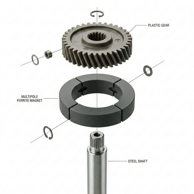
Ferrite Magnet Adhesive Bonding and Structural Assembly: Adhesive Selection, CTE Mismatch Stress, Surface Preparation, and Push-Out Testing
Plan ferrite magnet adhesive bonding: compare adhesive families, screen CTE mismatch, control surface preparation, and define push-out tests for your RFQ.
Ferrite magnet adhesive bonding joins brittle sintered ceramic magnets to steel rotors, motor casings, aluminum carriers, and plastic fixtures without relying on threaded holes in the magnet. Structural adhesive bonding and mechanical encapsulation can distribute load over a larger area, but both need joint-specific design. Concentrated clamping loads, uncontrolled interference, or contact at a chipped edge can crack the ceramic.
Selection answer: Start with a toughened structural epoxy as one candidate for a controlled ferrite-to-metal joint. Compare acrylics where assembly speed or strain accommodation matters, and evaluate retaining compounds only where clearance and cure conditions suit the specific product. No adhesive family has a universal temperature rating or ferrite bond strength. Ask for the exact formulation, substrate preparation, cure schedule, and aged assembly test results before approving a substitution.
This guide helps mechanical engineers, supplier quality managers, and procurement leads turn operating loads into an assembly specification. It combines a reproducible thermal-displacement screening example, a six-family adhesive decision matrix, and a push-out test plan that distinguishes catalog coupon data from an assembly acceptance limit. It reports no original physical test results or customer performance data.
Reviewed: 11 November 2026. Scope: Global OEM sourcing and factory assembly of permanent ferrite magnet joints, covering surface-mounted rotors, interior permanent magnet (IPM) carriers, motor stator housings, pot assemblies, and sensor fixtures. This is an engineering design and procurement guide. Select qualification tests, including thermal cycling, chemical exposure, and destructive retention tests where relevant, from the actual service profile and customer requirements.
Sourcing custom ferrite magnets or sub-assembled rotors and stators?
Submit your motor envelope drawings, operating temperature profile, and push-out force requirements for an end-to-end design review.
Explore Ferrite Rotor Assemblies
1. The Physics of Bondline Shear Stress: Differential Thermal Expansion (Δα)
When an electromechanical assembly changes temperature, the magnet and its carrier may expand and contract at different rates. Use the actual minimum temperature, maximum temperature, exposure duration, and cure history; an automotive temperature range is not automatically appropriate for an industrial pump or cabinet catch.
Understanding Anisotropic Ceramic CTE
For an oriented ferrite grade, request the coefficient of thermal expansion (CTE, α) in the directions relevant to the joint. Do not assign one generic ferrite value to every grade or orientation. Carrier CTE also depends on alloy, temperature, and, for reinforced polymers, molding direction and moisture condition.
The free differential thermal strain is a useful first screening quantity:
Δε = |α_substrate - α_ferrite| × ΔTHere ΔT is the temperature change from an assumed stress-free reference condition. Cure shrinkage and relaxation can shift that reference. The glass transition temperature (Tg) is not automatically the stress-free temperature.
Screening Displacement Before Calculating Stress
For a straight overlap of length L with an assumed symmetry point at its center, estimate the free displacement difference at an end and divide by the adhesive thickness ta:
Δu_free = |α_substrate - α_ferrite| × |ΔT| × L / 2
γ_screen = Δu_free / ta
Worked example, using assumed inputs: Let the CTE difference be 10 × 10^-6/K, the temperature change 100 K, the overlap 20 mm, and the adhesive thickness 0.10 mm. The free end displacement is 0.010 mm and γ_screen is 0.10, or 10%. At 0.02 mm thickness the same screening ratio becomes 50%. These are kinematic comparisons, not measured adhesive strains or allowable limits.
Multiplying this ratio by a constant shear modulus would give only an idealized linear-elastic stress estimate. It is not a Volkersen solution or a reliable peak edge stress: it omits adherend stiffness, curvature, peel, cure shrinkage, yielding, creep, and temperature-dependent properties. Use a validated joint model or FEA and physical tests for release.
Design implications:
- Control thickness: A starved joint increases the displacement demand per unit adhesive thickness. Increasing thickness also changes stiffness, void risk, and magnetic spacing; thicker is not always better.
- Request temperature-dependent data: Toughening, flexibility, and heat resistance are separate properties. Review modulus, creep, and retained strength across the duty cycle rather than selecting by room-temperature strength alone.
- Review segment length: Shorter segments may reduce accumulated mismatch displacement, but introduce more edges and assembly operations. Validate the complete geometry rather than assuming segmentation guarantees lower peak stress.
Substrate Compatibility & CTE Comparison
| Substrate Material | CTE Input for Screening | Mismatch Question | Design Trade-Off | Evidence Needed Before Release |
|---|---|---|---|---|
| Sintered Strontium Ferrite | Grade- and direction-specific supplier data | Which orientation lies along the overlap? | Ceramic fracture may govern before adhesive failure | Magnet grade, orientation, dimensional inspection |
| Low-Carbon Mild Steel | Alloy data over the temperature interval | Is the mismatch actually small for this ferrite direction? | Corrosion and cleanliness can dominate a close CTE match | Surface condition and aged joint results |
| Cast Iron / Ductile Iron | Casting grade data | Do porosity or surface residues change bonding? | A nominally favorable CTE does not establish adhesion | Qualified cleaning and preparation process |
| 304 / 316 Stainless Steel | Alloy and condition data | What displacement occurs at the cold and hot endpoints? | Passive surfaces affect some cure systems | Adhesive/activator compatibility and thermal tests |
| Cast / Extruded Aluminum | Specific alloy data | Does mismatch exceed the joint's validated strain accommodation? | Compliance competes with stiffness and hot creep | Thermal model, surface treatment, aged assembly tests |
| Glass-Reinforced Polymer | Directional, temperature- and moisture-dependent data | Are flow direction and conditioning represented? | Flexibility alone does not establish adhesion to the polymer | Molded-part trials and dimensional aging |
2. Joint Architecture and Bondline Gap Control
One important manufacturing risk is joint starvation. Magnetic attraction or excessive fixture pressure can squeeze wet adhesive from between a magnet and its carrier. A visible perimeter fillet does not prove that the intended contact area is bonded. Inspect adhesive volume, seating depth, and representative sections during process development.
Catalog images throughout this guide illustrate parts and inspection concepts. They are not records of a qualified bond, a measured push-out test, or a customer installation.
Selecting a Bondline Envelope
An initial trial might compare gaps such as 0.08, 0.12, and 0.20 mm, only if the chosen adhesive supports them. These are example experiment settings, not a universal ferrite specification.
- Lower limit: Account for ceramic roughness, carrier form error, adhesive wetting, and fixture repeatability. Prevent hard contact and dry patches.
- Upper limit: Review the product's gap capability, cure behavior, void sensitivity, and creep. Where adhesive occupies a magnetic flux path, include its thickness in the magnetic circuit model.
Engineering Methods for Guaranteed Bondline Spacing
- Supplier-Approved Spacers: Calibrated solid glass beads can help control thickness, but bead size, concentration, mixing, and local contact pressure require validation. Prefer an adhesive supplied with spacers or obtain written approval before modifying a formulation. ASTM D1002 is a coupon test method, not a glass-bead compliance specification.
- Molded Ribs or Standoff Dimples: Carrier features can establish a seating datum. Check that they do not point-load the ceramic or block adhesive flow; their height belongs in the tolerance stack.
- Curing Fixtures with Mechanical Stops: A fixture should establish the required envelope and support the magnet without uncontrolled force. Verify actual assembled gap across part tolerances and remove the fixture only after the specified handling strength is reached.
Visualizing the Structural Adhesive Joint Interface
The diagram below details the micro-architecture of a properly engineered ferrite-to-steel adhesive joint, highlighting the role of glass bead standoffs, surface wetting, and stress mitigation.
3. Adhesive Chemistry Selection Matrix for Ferrite Assemblies
Selecting an adhesive requires balancing thermal exposure, load direction, cure cycle time, gap capability, and chemical exposure. Compare exact products on the actual ferrite and carrier surfaces. A family name does not establish retained strength, Tg, cure time, or resistance to a specific coolant.
PRODUCT SHORTLIST -> COUPON SCREEN -> ACTUAL-JOINT TRIAL -> AGED JOINT TEST
Compare substrate, gap, cure, temperature, and failure mode at every step.
Use this six-family matrix to build a shortlist, not to assign a numerical strength rating:
| Adhesive Chemistry | Why Shortlist It | Process Controls | Main Selection Boundary |
|---|---|---|---|
| 1-Component Heat-Cure Toughened Epoxy | Candidate where controlled oven curing is available | Storage life, dispense temperature, actual joint temperature, time at cure temperature | Verify magnet, coating, carrier, and insulation tolerate the cure; heat cure alone does not establish hot strength |
| 2-Component Toughened Structural Epoxy | Candidate for structural ferrite-to-metal assemblies without a mandatory oven process | Exact mix ratio, static mixer, purge volume, working time, full cure | Handling strength is not full cure; test creep and fluid exposure on the selected formulation |
| Structural Acrylic / Methacrylate | Candidate when rapid handling or impact tolerance is important | Product-specific mixing or activator procedure, open time, ventilation, substrate compatibility | Not every acrylic is flexible or compatible with every plastic, coating, or ferrite surface |
| Anaerobic Retaining Compound | Candidate for close-fitting cylindrical joints | Clearance, exclusion of air, substrate activity, approved activator, cure depth | Ferrite and passive metals can alter cure; do not assume a metal-to-metal cure rate applies |
| 1K/2K Structural Polyurethane | Candidate when compliance and vibration accommodation are priorities | Moisture sensitivity, mix or moisture-cure conditions, section depth | Check hot creep and hydrolysis resistance; flexibility does not establish structural retention |
| Acrylic Pressure-Sensitive Adhesive (PSA) | Candidate for non-critical positioning, signage, and suitable stationary fixtures | Surface preparation, application pressure, dwell, contact area | Sustained load, temperature, and peel govern; do not transfer a tape's static rating to a rotating magnet assembly |
For a concrete process example, the 3M DP420 Black product page identifies a 2:1 mix ratio, a 20-minute working time, and full cure after 24 hours at room temperature. These are product-specific handling data, not proof of suitability for ferrite rotors. Its short paint-bake exposure rating must not be read as a continuous service-temperature rating. Obtain the applicable regional technical data sheet before planning a production cycle.
For an assembly quotation, send the shortlisted adhesive data sheets with your drawing and request a ferrite bonding review. Identify who owns adhesive approval and whether the quoted scope includes bonding, inspection, and destructive test samples.
4. Surface Energy, Cleanliness, and Primer Protocols
Surface preparation is a critical process variable. Ground ferrite surfaces can retain ceramic dust, coolant residues, and oils. The carrier may add corrosion products, release agents, or coatings. Define both surfaces in the work instruction; cleaning the magnet alone does not qualify the joint.
The Ceramic Porosity and Surface Dust Trap
If adhesive bonds to loose dust rather than sound ceramic, the weak boundary layer can separate under load. A clean-looking surface can still carry contamination. Compare the chosen preparation process against actual-joint strength and failure location, including after environmental exposure.
UNWASHED FERRITE DEFECT MECHANISM:
Adhesive Bead  -->  [ Microscopic Ceramic Swarf Layer ]  -->  Bulk Ferrite
                                  ||
                        (Fails at dust boundary!)
The 4-Stage Cleaning Specification for Mass Production
Develop and qualify a preparation sequence with the magnet and adhesive suppliers. No cleaning recipe guarantees cohesive failure, and fracture within the ferrite also needs evaluation:
- Stage 1: Remove Particles and Oils:
- Select an adhesive-compatible aqueous or solvent process. Ultrasonic cleaning is an option if trials show it does not damage edges or redistribute contamination.
- Record cleaner concentration, bath condition, time, temperature, and handling precautions. Validate changes rather than adopting a generic bath recipe.
- Stage 2: Remove Cleaning Residues:
- Where an aqueous process requires rinsing, control rinse quality and drainage. Confirm that the cleaned carrier will not flash-rust before bonding.
- Stage 3: Dry and Protect:
- Establish drying conditions compatible with the magnet, coatings, and carrier. Define a maximum clean-to-bond interval and prevent contact with dirty gloves, trays, or compressed-air lines.
- Stage 4: Verify the Process:
- Combine a particle/residue inspection with a wetting screen where suitable, and correlate the process with destructive joint tests.
- Dyne pens measure wetting behavior under a particular procedure; a single reading cannot prove dust removal or bond readiness on rough, porous ferrite. ISO 8296 and ASTM D2578 concern plastic-film wetting measurements, not a universal ceramic acceptance threshold. Use sacrificial witness parts if test fluids could contaminate production surfaces.
Silane Coupling Agents and Surface Primers
An adhesive supplier may recommend a silane coupling agent, adhesion promoter, or anaerobic activator. These have different functions and are not interchangeable. Compare primed and unprimed joints after relevant humidity or fluid exposure. Control primer identity, dilution where applicable, coverage, flash-off, and shelf life. A primer can improve a qualified process; it does not eliminate hydrolytic degradation or compensate for loose dust.
5. Mechanical Retention, Rotor Wedges, and Anti-Lift Safeguards
For rotating machinery, evaluate magnet retention as a complete load path. A high room-temperature coupon strength does not establish resistance to centrifugal loading, hot creep, vibration, overspeed, or a single process defect. Determine the need for mechanical containment through the assembly risk assessment and applicable product requirements.
Centrifugal Force Dynamics on Motor Rotors
In surface-mounted permanent magnet (SPM) rotors, the centrifugal force pulling a magnet radially outward against the adhesive bondline is governed by:
F_centrifugal = m × r × ω²Where m is magnet mass (kg), r is the center-of-mass radius (m), and ω is rotational velocity in radians per second (ω = 2π × RPM / 60).
This equation gives the radial force on one magnet for the assumed mass, radius, and speed. It does not give local adhesive stress or a safe speed. Edge peel, load sharing, temperature, geometry, balance, and containment need separate evaluation; there is no universal RPM threshold for adding a sleeve.
Mechanical Hybrid Retention Strategies
- Metal Retention Sleeves: Size the sleeve, interference, assembly method, and thermal fit as a system. Check ceramic contact pressure, magnetic effects, and eddy-current heating. Do not assume that a nominal stainless grade remains non-magnetic after forming or that the sleeve automatically carries all radial load.
- Composite Banding: Fiber orientation, winding tension, resin temperature capability, and defects determine retention. Carbon and glass systems have different electrical and mechanical properties; a fiber tensile-strength value alone cannot rate a finished sleeve.
- Interior Magnet Cavities: Rotor bridges can provide radial restraint, while adhesive or potting may limit axial movement and vibration. Qualify bridge stress, voids, and retention together.
- Stator Spring Retainers: Clips can supplement bonding in stationary housings. Define contact area, preload, tolerances, fatigue, and corrosion resistance to avoid damaging the ferrite while maintaining restraint.
6. Repairability and End-of-Life Disassembly
Ask whether the assembly must be repairable or separable at end of life before selecting a permanent bond. This section is a design and sourcing checklist; it makes no claim that a particular adhesive, debonding temperature, or product passport field is legally mandatory for every ferrite assembly.
The Recycling Dilemma of Irreversible Epoxies
A durable thermoset may make recovery of intact magnets or clean separation from the carrier difficult. Evaluate recovery objectives with the actual recycler or service organization. Do not assume that heating a bonded rotor releases it cleanly or leaves its insulation, coatings, magnetic properties, and structural performance unchanged.
Designing for Disassembly (DfD)
Include three practical questions in the RFQ:
- Release mechanism: Can accessible retainers, a replaceable carrier, or a supplier-qualified debonding adhesive meet the service-life requirements and the intended separation method?
- Process boundaries: What temperature, solvent, force, and handling controls are required? Obtain a documented procedure and a trial result. Adhesive decomposition can create hazardous emissions and residues; it is not equivalent to a validated clean-release process.
- Documentation: Record adhesive product and revision, relevant safety information, assembly location, and agreed disassembly instructions. Confirm any market-specific documentation obligations separately with the responsible compliance team.
7. Quality Assurance: Push-Out Testing, Thermal Shock, and FAT Standards
Validating a bonded magnetic assembly requires quantitative, destructive and non-destructive Factory Acceptance Testing (FAT). Never rely on subjective "tap tests" or visual fillet inspections alone.
The Push-Out Shear Force Calculation
For a cylindrical joint, axial push-out testing measures assembly retention in a specified fixture. To compare results, calculate an apparent average stress from the effective bonded area. A nominal force estimate can also be calculated from an independently qualified design stress:
A_effective = π × D_bond × L_bond × bonded_fraction
τ_apparent = F_measured / A_effective
F_nominal = A_effective × τ_design
Where:
- D_bond is the diameter of the bonded interface (mm), not automatically the magnet outside diameter.
- L_bond is the bonded axial length (mm); bonded_fraction accounts for deliberately unbonded sectors or channels.
- τ_design is an assembly-specific design input (MPa or N/mm²), established with appropriate load, aging, variability, and safety margins. A catalog lap-shear value is not this input.
Arithmetic example, not a validated rating: Assume a fully bonded cylindrical interface with D = 40 mm, L = 25 mm, and a hypothetical τ_design = 12 MPa:
Area = π × 40 mm × 25 mm = 3,141.6 mm²
F_nominal = 3,141.6 mm² × 12 N/mm² = 37,699 N (approx. 37.7 kN)
A measured breakaway force of 15 kN would correspond to about 4.77 MPa apparent average stress for that full area. It is a rejection only if it violates an approved assembly limit. The calculation alone cannot diagnose contamination, incomplete cure, ceramic fracture, fixture misalignment, or friction. Record the force-displacement curve and inspect the failure surfaces.
The ISO 4587 scope explicitly distinguishes standardized lap-shear testing from design information. ASTM D1002 likewise concerns metal single-lap coupons; neither should be presented as a direct cylindrical push-out acceptance procedure. Define an assembly-specific fixture and method instead.
Define the Qualification and Factory Acceptance Plan
Qualification establishes whether the design and process meet the application; factory acceptance checks agreed production characteristics. Destructive push-out samples are normally sacrificed. Do not proof-load every saleable assembly unless a validated non-damaging proof procedure and customer agreement support that approach.
- Baseline and Fixture Definition:
- Specify support diameter, ram contact face, alignment, loading direction, crosshead speed, measurement calibration, and test temperature. Prevent the ram or support from breaking the ceramic before the intended interface is loaded.
- Fix cure age, sample count, lot coverage, and whether the recorded result is first movement, peak force, or another event. Crosshead speed must be justified for this fixture, not copied from a lap-shear method.
- Environmental Exposure:
- Select thermal cycling, humidity, actual fluid chemistry, vibration, and corrosion exposures from the service profile and customer requirements. State endpoints, ramps or transfers, dwell, duration, and exposure sequence.
- Distinguish hot testing from room-temperature testing after recovery; cooling can mask loss of hot strength. Neither a generic cycle count nor a retained-strength percentage is universally mandatory for ferrite joints.
- Release Criteria and Traceability:
- Agree absolute minimum retention and any aged-to-baseline comparison before testing. Apply the criteria to individual results as specified; a passing mean should not hide weak specimens.
- Retain serial or batch IDs, adhesive lot and expiry, mix/dispense records, preparation history, cure trace, measured gaps, failure photographs, and disposition. Ceramic fracture needs its own assessment rather than an automatic adhesive pass.
8. OEM Procurement and Engineering Verification Checklist
Before releasing purchase orders or freezing engineering drawings for custom ferrite magnet bonded assemblies, verify these eight critical technical parameters:
- 1. Materials and Duty: Identify ferrite grade and orientation, carrier material/coating, directional CTE inputs, temperature history, loads, and fluids.
- 2. Bondline Datum: Define the qualified minimum/maximum gap, bonded area, tolerance stack, spacer approval, and seating inspection method.
- 3. Adhesive Identity: Specify manufacturer, exact product and revision, storage, cure schedule, and approved substitution process. Request temperature-dependent strength and creep data rather than relying on a generic Tg margin.
- 4. Surface Preparation: Agree cleaning, residue checks, drying, maximum clean-to-bond time, and process monitoring on both substrates.
- 5. Primer Decision: Record whether a primer or activator is required by the qualified adhesive process, with product identity, application, and aging evidence.
- 6. Mechanical Retention: Review radial and axial load paths, ceramic contact stress, maximum/overspeed conditions, and containment requirements with the responsible designer.
- 7. Push-Out Acceptance: Approve the fixture, loading rate, test temperature, cure age, sample plan, absolute force limit, aging requirements, and failure-mode reporting.
- 8. Commercial Release: Assign design approval, test costs, destructive-sample allowance, traceability, change notification, and any agreed service/disassembly documentation before the purchase order.
Visual Decision Aids
Read the diagram as a sourcing sequence: define the RFQ scope, validate the joint envelope, test a pilot lot, and lock the supplier control plan. Envelope review includes thermal mismatch and gap tolerances; pilot testing includes the selected preparation, adhesive, cure, and environmental conditions. A failed or undocumented gate returns the assembly to engineering review before production release.
Decision Snapshot
The table below connects common assembly risks with the evidence an OEM buyer should request. Numerical limits belong in the approved drawing and test plan:
| Operating Constraint / Assembly Challenge | Root Engineering Phenomenon | Required Engineering / Process Action | Sourcing Acceptance Release Boundary |
|---|---|---|---|
| Thermal Cycling | Differential expansion, modulus changes, and fatigue | Screen displacement and validate the actual joint across its duty cycle | Approved absolute and aged retention criteria, with failure records |
| Aluminum Housing Pairing | Carrier/magnet mismatch and surface-treatment sensitivity | Compare qualified adhesive products and surface treatments | Results on the specified alloy, coating, gap, and ferrite grade |
| Grinding Swarf Contamination | Weak boundary layer beneath the adhesive | Qualify particle removal, degreasing, drying, and protected handling | Process records correlated with actual-joint strength |
| Joint Starvation | Magnetic or fixture force squeezes out adhesive | Control dispense volume, seating, and approved spacing method | Representative gap/coverage inspection and tolerance evidence |
| Rotating Magnet Retention | Radial loading, edge peel, hot creep, and imbalance | Assess bond and mechanical containment as one load path | Design review and application-specific spin/retention qualification |
| Service or End-of-Life Separation | Durable bonds can obstruct recovery | Agree accessible retention or a qualified separation method | Documented trial, material limits, handling controls, and responsibilities |
Structural Bonding Engineering Recommendation
Select adhesive and retention geometry together, using thermal mismatch screening and tests on the actual ferrite-to-carrier joint.
Recommended Action
Approve a controlled gap, supplier-supported surface preparation and cure, and a documented push-out sampling plan with application-specific aged retention limits before volume release.
Caution
Catalog lap-shear strength, a wetting-pen reading, and the worked force example do not establish a safe assembly rating. Evaluate ceramic contact stress and the complete retention load path.
For custom-machined ferrite magnets, bonded rotor assemblies, and precision sub-systems, explore our specialized manufacturing capabilities across Ferrite Rotor Assemblies, Ferrite Motor Stators, Adhesive-Backed Ferrite Profiles, Ferrite Pot Magnets, and Custom Machined Ferrite Components. Contact our applications engineering group to review your assembly drawings, joint stress calculations, and quotation scope.
Frequently Asked Questions
Can standard cyanoacrylate (super glue) be used for production ferrite assemblies?
Do not approve an unspecified household super glue for a structural magnet joint. Engineered cyanoacrylate formulations vary in toughness, gap capability, temperature resistance, and moisture performance. If one is shortlisted, require manufacturer-supported use conditions and actual-joint qualification. A temporary fixturing adhesive must also be checked for compatibility with the structural adhesive.
Why do ferrite magnets crack when press-fit into steel sleeves?
Ferrite is brittle, so uneven contact, edge defects, excessive interference, or thermal fit changes can initiate fracture. The stress state depends on whether the magnet is inside a sleeve or around a shaft; it is not universally tensile hoop stress. Specify a designed fit and assembly method that limit ceramic stress, with a qualified adhesive clearance where bonding is used. A generic clearance number cannot replace a tolerance and load analysis.
What is the role of glass microspheres in structural magnet adhesives?
Approved solid glass spacers can limit squeeze-out and help establish a repeatable gap. Their size is a design input, not a universal 100–150 μm requirement. Bead distribution, part form, fixture force, and local ceramic contact stress still affect the joint. Do not add beads to a commercial adhesive without supplier approval and requalification of the resulting process.
How does oil or coolant immersion affect bonded ferrite magnets?
Evaluate the complete assembly in the actual fluid formulation and temperature range. Adhesive softening, swelling, corrosion of the carrier, and attack on coatings or the ferrite surface can change retention. Do not claim universal resistance to mild acids or every coolant additive. Request exposed-joint strength and failure-mode data; a generic chemical-resistance chart is only a screening aid.
How do we verify that ceramic grinding dust has been removed prior to bonding?
Use a validated particle/residue inspection and correlate the cleaning process with destructive bond tests. Microscopy or a defined wipe check may help monitor loose particles. Wetting tests can screen some contamination, but roughness, porosity, and test-fluid absorption affect results. No single dyne value proves that ferrite grinding dust has been removed.
Evidence and Applicability Notes
Evidence and Applicability Notes
Last reviewed: 2026-11-11
Sources Used
- ISO 4587:2003: International standard for tensile lap-shear strength determination of rigid-to-rigid bonded assemblies.
- 3M DP420 Black product information: a specific example of mixing, working time, and cure requirements.
- 3M DP420 family technical data sheet: manufacturer test conditions and product-specific performance context; obtain the current regional revision.
Method
- Editorial engineering synthesis with an assumed-input thermal displacement calculation; no peak-stress solution or physical test is claimed.
- Compared six adhesive families qualitatively and separated a named manufacturer process example from assembly qualification.
- Reproduced cylindrical bonded-area arithmetic using a hypothetical design stress; no acceptance limit is established by that example.
Applicability Boundary
- This guide provides engineering design principles and procurement screening; it does not replace finite element analysis (FEA) or physical validation on serialized prototypes.
- Product handling data apply only to the identified formulation and conditions; illustrations and worked examples are not factory test evidence.
- Qualification exposures and acceptance limits must be defined for the application and agreed by the responsible designer and customer.
Related Internal Guides
- Ferrite Rotor Assemblies Product Catalog
- Ferrite Motor Stators Manufacturing Specifications
- Adhesive-Backed Ferrite Magnets and Profiles
- Ferrite Pot Magnets and Channel Assemblies Sizing Guide
- Radial Multipole Ferrite Rings for BLDC Motors
- Ferrite Arc Segments for Motor Stators: Engineering Sizing and Camber Fit
- Visual Acceptance Standards for Ferrite Magnets: Chipping and Cracks
- Ferrite Magnet Tolerance Guide for Mass Production
- Low-Temperature Demagnetization in Ferrite Magnets: An OEM Sourcing Guide
- Ferrite RFQ Checklist for OEM Buyers
External References
These sources provide test-method scope and manufacturer context. They do not establish a universal ferrite joint specification. Standardized coupon methods and manufacturer data must be supplemented by qualification of the actual assembly:
- ISO 4587:2003 — Tensile lap-shear testing of rigid-to-rigid bonded assemblies: The public abstract identifies a standardized test procedure and states that it does not provide design information. Consult the full applicable edition for coupon work.
- 3M Scotch-Weld DP420 Black — Manufacturer product information: A product-specific example of working time, mixing, cure, and exposure limitations, not a ferrite assembly approval.
- 3M Scotch-Weld DP420 family — Technical data sheet: Published manufacturer test-condition context for the named product family. Treat this family document as background and request the latest regional sheet for the exact formulation; its coupon data are not design allowables for a ferrite joint.
Author

Categories
More Posts

Draft Research: Ferrite Packaging Logistics
Draft notes

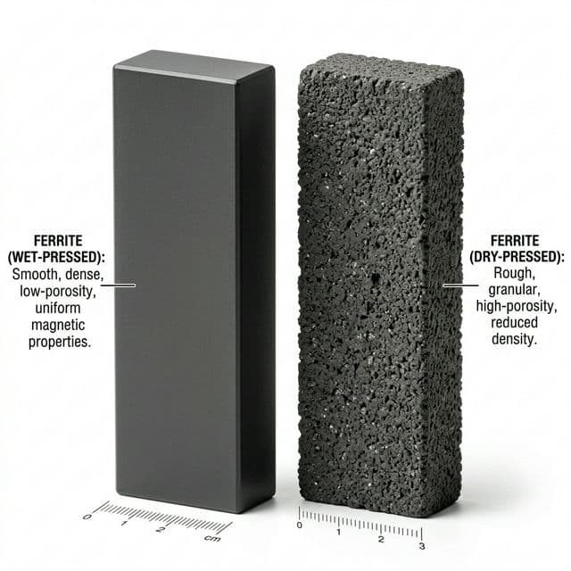
Anisotropic Ferrite vs Neodymium: 2026 Engineering Decision Guide
Compare anisotropic ferrite vs neodymium on force density, thermal limits, and supply risk. Use RFQ gates to request a project-specific engineering review.
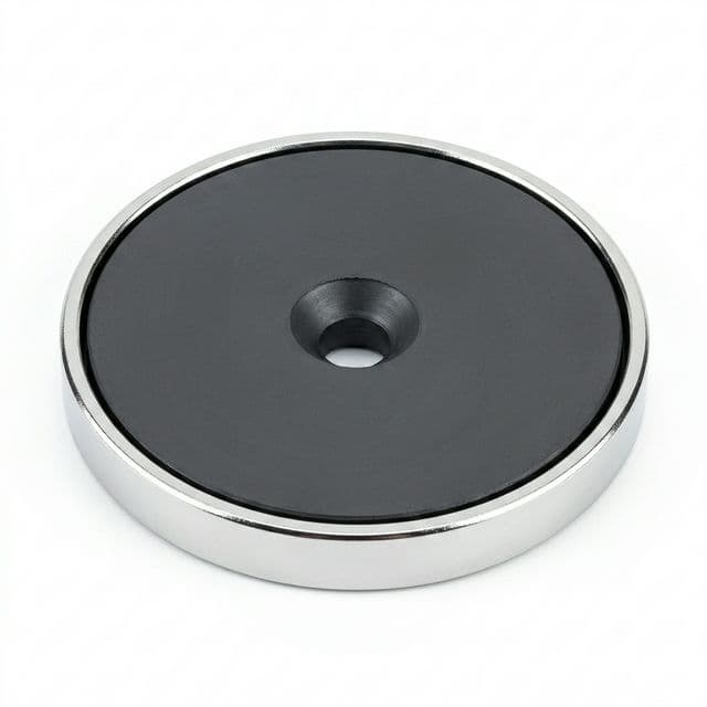
Ferrite Pot Magnets and Channel Assemblies: Magnetic Circuit Sizing, Holding Force Physics, and Sourcing Controls
Specify custom ferrite pot magnets and channel assemblies: optimize steel cup thickness, calculate air-gap decay, prevent shear slip, and secure OEM RFQs.
Inquiry Email
Copy the email, or open your default email app to start an inquiry.